Testing of a four-channel Stokes polarimeter performance for intrusion detection in QKD systems
Estera Pawlikowska1*
Marek Życzkowski1
Anna Pakuła2
Paweł Marć3
- Institute of Optoelectronics, Military University of Technology, ul. gen. Sylwestra Kaliskiego 2, 00-908 Warsaw, Poland
- Institute of Micromechanics and Photonics, Warsaw University of Technology, ul. św. Andrzeja Boboli 8, 02-525 Warsaw, Poland
- Faculty of Advanced Technologies and Chemistry, Military University of Technology, ul. gen. Sylwestra Kaliskiego 2, 00-908 Warsaw, Poland
Article Info
Received 04 Jul. 2024
Received in revised form 26 Nov. 2024
Accepted 02 Dec. 2024
Available on-line 11 Feb. 2025
Keywords: quantum key distribution; Stokes polarimeter; polarimetric sensor; fibre violation.
Abstract
The most mature quantum key distribution systems available on the market is the class of prepare-and-measure systems which are vulnerable to eavesdropping attacks. Therefore, monitoring optical properties of such a system should be enhanced. This paper presents a measurement methodology, characterisation, and testing of a four-channel Stokes polarimeter implemented into the send-and-return quantum key distribution system with faint pulses. The developed polarimetric setup is a complete amplitude-division Stokes polarimeter, the main objective of which is to define changes in the polarization state of light pulses. The measurement method is based on intensity measurements of four selected polarization components. The four-channel Stokes polarimeter was characterised and its performance was compared with a commercial instrument. At this stage of the polarimeter development, different signal processing paths were proposed. The influence of fibre infringement was observed as a rapidly changing polarisation state and, as a result, intrusion threshold levels were determined for the analysed signals for the quantum key distribution fibre-optic link tested.
Introduction
The rapid development of quantum computing is a real threat to the security of information encoded by classical cryptography. Hence, a two-way strategy is being implemented as countermeasures, i.e., postquantum cryptography [1–3] and hardware-based secret key distribution, especially quantum key distribution (QKD) [4]. QKD enables a secure key exchange between parties and, in theory, provides unconditional security of information [5–7] due to fundamental laws of quantum mechanics. Real systems show imperfections and vulnerabilities despite the theoretical QKD unconditional information security. The most mature QKD systems described in [8–11], also commercially available [12, 13], are designed in a prepareand- measure configuration. These methods based on faint light pulses offer relatively high exchange key rates and easy implementation with commercially available telecommunication elements. However, the communication channel in QKD systems is exposed to a potential eavesdropping, making it challenging to achieve absolute security [4]. One way to deal with systems loopholes is through protocol modification, while another consists of improving physical systems enhancing security. For the best security, the two approaches may be integrated into a single system cooperatively. There is possibly another approach, still in the early stage of implementation, that is the utility of device-independent QKD measurement or even device-independent QKD based on entanglement [4].
In an optical fibre, constant, slow changes in the ellipticity and azimuth angle of the propagated light in the state of polarization (SOP) are observed [14]. Cumulatively, such changes in the optical fibre are named polarization drift, which has generally random characteristics. Changes in SOP result from temperature drift, pressure, as well as stress and strongly depend on the fibre length [15]. For longer optical fibres, the polarization drift over time, defining the speed of changes of SOP, shortens. The influence of polarization variations on fibre-based QKD systems was featured by Ding et al. [15].
They examined changes of SOP in polarization-sensitive QKD systems, like phase-encoded one-way systems based on the asymmetric Mach-Zehnder interferometer. Reference 16 presented the influence of polarization drift in QKD systems with the polarization coding and the method of heuristic polarization compensation. Furthermore, the approach dealing with environmental disturbances in a one-way QKD system was featured [17]. In 2006, MacDonald [18] proposed a polarimetric-based method for monitoring intrusions in fibre-optic links, based on continuous control of SOP of the light propagating in the fibre. Single-mode fibres (SMFs) are remarkably sensitive to external conditions, especially stress, and temperature [14, 15], which manifests as changes in the SOP of the propagating light. In the SMF, this is related to birefringence distribution over length, which is generally considered random [19]. Due to high sensitivity, as it was demon-strated, optical fibres, particularly SMFs, are successfully applied in pressure [20, 21], stress [22], and temperature sensing systems [23]. Stokes parameters, optical power, and degree of polarization are the most promising parameters that can be used to monitor a fibre-optic link. Taking sensitivity under consideration, Stokes parameters are the most susceptible to an external influence changing the SOP [24].
During an eavesdropper attack, a fraction of light is decoupled to yield transmitted information. The optical loss change in a fibre-optic link is vestigial and invisible to the electronic detection system. However, if the eaves-dropper’s attacks consist of only a mechanical disturbance of the optical fibre, one can expect significant changes in birefringence and measurable perturbances of the SOP [25]. Distinguishing between measured slow time changes of the SOP and abrupt changes caused by an attack is possible with a fibre-optic sensor system that allows monitoring intrusions into a fibre-optic link infrastructure [24]. Following this assumption in [20], a fibre-based pressure sensor was presented, where the pressure value was obtained from the measured Stokes parameters.
Optical fibre tapping methods, such as macro and micro bending, optical splitting, evanescent decoupling, and V‑groove cut, etc. require direct access to the optical fibre and removal of the outer plastic jacket and coating [26]. Such actions induce additional stresses and bring instant, higher changes in the birefringence. This can be detected based on polarimetric measurements. Slow-time changes are caused due to variable environmental conditions, while rapid changes correspond to the fibre infringement.
The main objective of this work is to detect fast changes of the SOP of the propagating light, which would result from the physical infringement of the optical fibre. In this approach, the measurement of the SOP for a light pulse and the calculation of the difference of this parameter between the following pulses should be performed. In the case of short pulses, the SOP of each pulse cannot be analysed in time using rotating or oscillating phase elements. There-fore, the authors introduced a polarimetric system with a division of the amplitude [27–30].
The paper presents the performance of a developed four-channel Stokes polarimeter (FCSP) system for detecting optical fibre violations based on monitoring changes in the polarization of the light pulse over time. The FCSP was implemented in a QKD system working in the faint-pulses regime, enriching it with sensing properties and enhancing its immunity from cyber-attacks on the quantum fibre-optic link infrastructure.
Nowadays, the most vivid technology of QKD networks is a point-to-point architecture [31]. While using faint pulses with send-and-return systems, the authors’ solution might be used between optical trusted nodes.
Determination of the Stokes vector
The full definition of SOP requires at least four inde-pendent intensity measurements corresponding to different input polarization components, i.e., linear horizontal, vertical, and one of each linear diagonal or antidiagonal and one circular. Mueller calibration matrix calculates the Stokes vector characterising the polarimeter. Stokes vector parameters [32] are a linear combination of intensities measured for different polarization components and they can be written as a matrix equation where the transfor-mation of the measured intensity I, in general, may be described as [32]:
\( I=A S \) (1)
where S is the searched Stokes vector describing the SOP of the incoming light and A is the Mueller calibration matrix. This matrix expresses the transformation from the input Stokes vector S to a single intensity in each of the polarimeter channels and can expand to A = RT. R is the responsivity matrix:
\( \mathbf{R}=\left[\begin{array}{cccc} r_0 & 0 & 0 & 0 \\ 0 & r_1 & 0 & 0 \\ 0 & 0 & r_2 & 0 \\ 0 & 0 & 0 & r_3 \end{array}\right] \) (2)
where ri are the parameters describing channels of the used polarimeter and i is the number of the channel. Matrix T is a transformation matrix composed of the first rows of the channel Mueller matrices. It carries information on how the intensity of different polarization components is trans-mitted through particular channels and is built as [33]:
\( T(i)=I_0 M_i \) (3)
where Mi is the Mueller matrix channel, i is the channel number, and I0 = [1 0 0 0].
Based on all the above, the incident Stokes vector is obtained in the following way:
\( S=A^{-1} I \) (4)
To enable this operation, matrix A must be non-singular with the non-zero determinant [32].
Experimental setup
A novel method for intrusion detection within fibre-based QKD systems based on the continuous SOP measurement is proposed. The main objective of the FCSP as a sensor is a measurement of relative changes of SOP over time domain. In this paper, intrusions are defined as rapid, high-amplitude changes of SOP, while slow changes come from variations in external conditions.
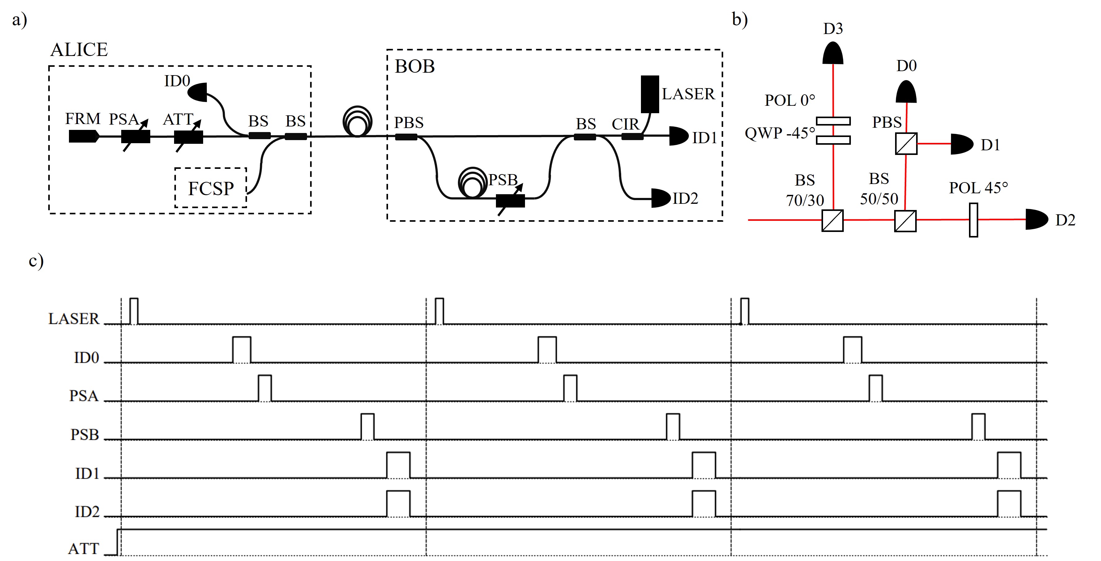
The examined QKD system is a send-and-return setup with differential phase-encoding [34, 35]. Fig. 1(a) presents the visualization of the system components. It consists of ALICE (sender) and BOB (receiver) units. Between the parties, an SMF exposed to eavesdropping attacks is led as a quantum channel. The system uses faint-light pulses posing a threat to multiphoton pulses. In this configuration, polarization changes in the fibre do not affect the system work as a result of using a Faraday rotator mirror (FRM).
The main purpose of the FCSP setup is to detect an SMF infringement. Transmitted light is monitored in a one-way transition where pulses are not yet attenuated. Therefore, the FCSP system is integrated with the ALICE setup where a part of the light can be decoupled. The FCSP gives information about normalized Stokes parameters. Since there is no reference for the total pulse intensity, the degree of polarization is assumed to be stable.
The FCSP is a full Stokes polarimeter with an amplitude division, enhanced by analysing four polarization compo-nents. Fig. 1(b) depicts the alignment of the FCSP optical elements. This configuration allows the analysis of SOP for selected light pulses. The incoming light is split into four paths of the optical setup, where a part of an input light beam is transferred through each channel and analysed as a distinct polarization component. The intensities of these components are measured with corresponding detectors. The horizontal (D0), vertical (D1), positive diagonal (D2), and right-handed circular (D3) components are analysed using various polarizing elements, including linear polarizers (POLs), beam splitters BSs, polarizing beam splitter (PBS), and quarter-wave plate QWP. The measurement is performed based on spatial multiplexing. The FCSP setup provides simultaneous measurement of all four intensity components, which is very important in investigating dynamic changes by maintaining the equality of the optical path in each arm.
Fig. 1(c) shows the synchronization of ON/OFF control signals for the crucial elements of the QKD system.
Methods
The FCSP system calibration precedes the measurement. During this process, relative responsivities for all detectors are measured to determine the responsivity matrix R (2). Then, for each arm of the setup, a channel Mueller matrix Mi [32] is determined using measurements carried out with a ThorLabs Polarimeter PAX1000IR2. The obtained matrices are normalized and contribute to the transformation matrix T (3).
PAX1000IR2 is a polarimeter based on a rotating QWP and a fixed POL. The SOP modulates with the rotation of the wave plate. After passing through the POL, the time-changing light output is measured with a photodiode. Due to the in-time measurement with the PAX1000IR2, it is impossible to conduct a simultaneous measurement and compare the commercial and the authors’ polarimeter in a pulse regime.
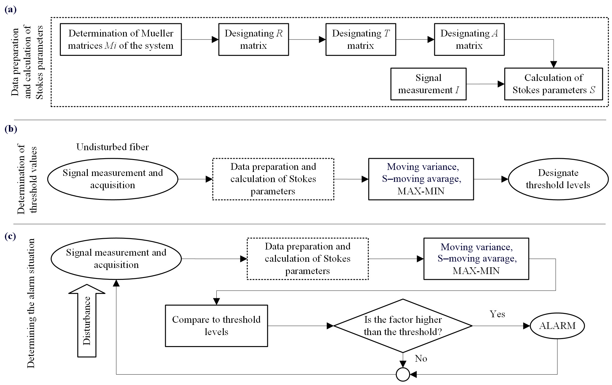
Block diagrams for signal processing in the FCSP system are presented in Fig. 2. The diagram in Fig. 2(a) shows how the data for Stokes parameters are prepared and calculated based on characterising matrices and measured signals upon formulas in section 2. Signals of four polarization components of the pulse are measured. Then, using the predetermined calibration matrix A, the Stokes vector S for each light pulse is designated (4) [33]. The measured signal I is proportional to the intensity of the light pulse.
Four arms of the FCSP analyse the SOP of the input light based on the intensities of different polarization components. The intensity of the pulses propagating in the fibre is assumed to be constant. This value is used to normalize the Stokes parameters.
After the calibration, sensing properties of the FCSP system were investigated using fibre spools of different lengths, i.e., 5 km and 8 km. The source was a continuous wavelength of 1550 nm with a 1 kHz chopper, imitating a pulsed light source. As an example of a direct attack on the fibre-optic link, the clip-on coupling method was chosen. Application of a clip-on coupler requires fibre preparation, i.e., striping all protecting jackets and coatings and a final clip-on installation. All these manipulations cause SOP changes in the optical fibre. Fibre preparation is relatively time-consuming and in this work it is simulated as touching and bending of the tested fibre. In addition, the third infringement concerns the introduction of a clip-on coupler. Repeated clip-on closing may induce damage to the stripped fibre, so the operation of the clip-on installation is simulated by using a standard 900 μm optical fibre in a plastic coating.
Three different disturbances were introduced to test the ability to detect attacks: touching, bending the fibre, and installing a clip-on coupler. Each disturbance was tested separately to designate the alarm threshold level.
Even though FCSP detects long-term changes, one can distinguish them from sudden disturbances using time-dependent factors. To detect rapid changes in SOP, three indicators can be introduced calculated from the measured Stokes vector S, i.e., the summed moving variances of the Stokes parameters (moving variance), the sum of the Stokes parameters with their moving average subtracted (S‑moving average), and MAX-MIN calculated as the maximum minus the minimum value of the Stokes parameter, summed for each Stokes, for a defined number of pulses.
The output signal processing method was developed based on the measurements. Fig. 2(b) depicts the steps of designating threshold levels for three alarm indicators. The diagram in Fig. 2(c) illustrates a signal analysis for detecting an alarm situation.
The intrusion is defined by simple thresholding of these indicators. The threshold level is set based on undisturbed fibre-optic link measurements and chosen as 110% of the maximum undisturbed signal level. The violation of the threshold values indicates a disturbance.
The FCSP final tests were conducted by its integration with the QKD system. The QKD system used is described in section 3 and works with light pulses of 2 ns at 1550 nm. For these tests, a standard SMF-based 1 km fibre-optic link was used. Due to the limitations of the processing system, one out of 100 pulses was measured.
The voltage signals from FCSP detectors are determined on the oscilloscope. Similarly to the previous tests, the authors examined three types of disturbances: touching, bending, and inserting a clip-on coupler.
Results and discussion
This section describes FCSP as a polarimetric sensor validation process and the results of SOP measurements during three kinds of fibre infringement. Measurements were conducted for standard SMF-based fibre-optic links and with QKD system integration.
Designation of the SOP
The performance of the FCSP setup was evaluated through SOP measurements during the rotation of a QWP placed in front of a linear POL. The validation was carried out using a commercial polarimeter. Fig. 3 illustrates the results of the measured SOP with both commercial polar-imeter (marked with blue dots) and FCSP (red dots), presented on the Poincaré sphere [36]. It was assumed that the degree of polarization was constant during the measurement.
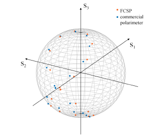
After validation of the FCSP, a mean absolute error (MAE) of azimuth and ellipticity angle was chosen concerning results obtained from commercial polarimeter measurements. The MAE values are as follows: for the azimuth, the MAE is 0.17 rad, and for the ellipticity angle – 0.02 rad. However, the FCSP work main objective is to measure changes of SOP. Due to the assumption that the measured changes are more significant than MAE values, the accuracy of SOP calculation is not crucial in the sensor application of the FCSP.
Testing sensing properties of the FCSP
The experiments for disturbance detection were conducted on two different SMF fibre-optic link lengths: 5 km and 8 km, named INDOOR and OUTDOOR, respectively. The names are based on installation places. The intrusion attempts were simulated by touching and manual bending the optical fibre, causing disruptions every 5 s, and connecting a clip-on coupler on a 5 km fibre which was opened and closed every 5 s.
Fig. 4 depicts the measurement results of three indicators showing variations of SOP for different events over time. Disturbances are observed as peaks, while the threshold level was set based on undisturbed fibre measurements as 110% of the maximum values. For better clarity, only representative results of the INDOOR fibre-optic link are presented. Based on the obtained results for each used, time-dependent indicator threshold levels were selected. All plots in Fig. 4 illustrate those levels as a red line. Detection effectiveness, understood as the percentage ratio of detected events to all, is presented in Table 1 for both INDOOR and OUTDOOR fibre-optic links measurements.
Table 1.
The effectiveness of disturbance detection of three factors for INDOOR and OUTDOOR fibre-optic links measurements while touching and bending the fibre and connecting a clip-on coupler.
Indicators |
Touching |
Bending |
Clip-on |
|
Moving variance |
INDOOR |
71.4% |
100% |
100% |
OUTDOOR |
97.1% |
100% |
100% |
|
S–moving average |
INDOOR |
97.1% |
100% |
100% |
OUTDOOR |
48.6% |
100% |
100% |
|
MAX-MIN |
INDOOR |
85.7% |
100% |
100% |
OUTDOOR |
94.3% |
100% |
100% |
|
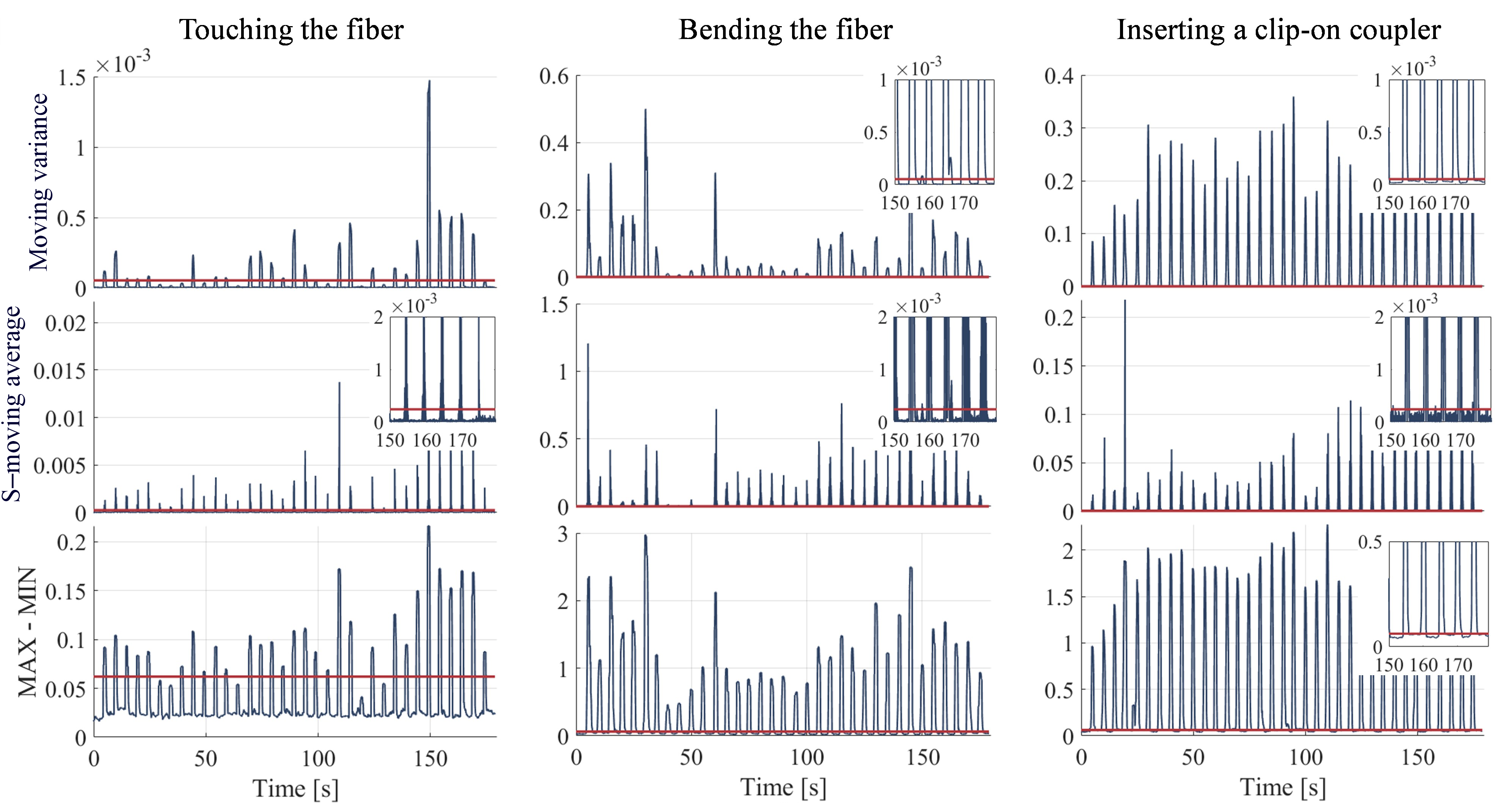
For bending and connecting the clip-on coupler, 100% of disturbance events were observable in all three implemented indicators. However, when touching the fibre, disturbance identification is inconsistent, and not all events were successfully detected. For the INDOOR fibre-optic link measurements S–moving average exhibits the highest detection effectiveness at 97.1%, while for the OUTDOOR fibre-optic link measurements, MAX-MIN shows the best effectiveness at the 94.3% level. Overall, in the case of the OUTDOOR fibre-optic link, the measurements were characterised by a higher noise level than the INDOOR fibre-optic link, which led to further fluctuations of SOP. However, a crucial impact on indicators levels and detection effectiveness had the force of introduced disturbances.
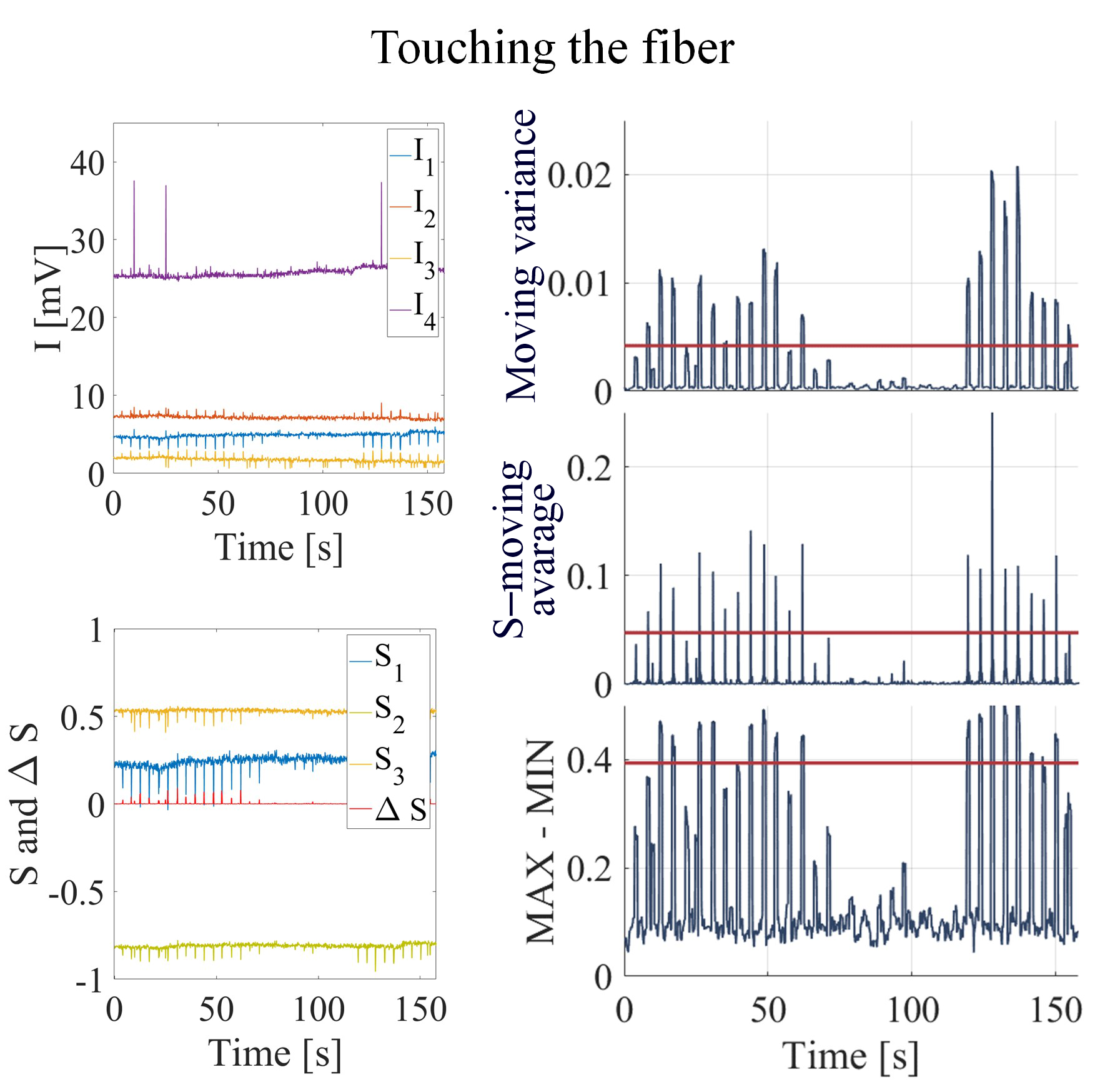
Disturbance detection in the QKD system
The detection of the disturbances in the QKD system was examined on a 1 km SMF fibre-optic link integrated with the ALICE part. The simulation of intrusion attempts was carried out as in previous measurements and the same indicators were used. Fig. 5 presents the results of the measured signals for touching the fibre. The top left graph represents measured signals I1, I2, I3, and I4. The Stokes parameters S1, S2, and S3 from these values, are calculated on the bottom left plot. The red line represents a square sum of Stokes parameters differentials – ΔS. The right column includes three plots with indicators described in the previous section, i.e., moving variance, S–moving average, and MAX-MIN. The observed peaks in these values are caused by touching the fibre and exceeding the threshold level is interpreted as an alarm situation.
Similarly, the results for bending the fibre and connecting a clip-on coupler are presented in Fig. 6 and Fig. 7, respectively. In the case of bending the fibre, the changes in calculated indicators are highly variable over time with peak levels significantly higher than those designated for touching. When connecting a clip-on compared to the former results, the S–moving average shows efficiency at a 44.4% level. The indicator values exceeding the threshold level without introduced disturbance are caused by calculation errors for extremely low pulse intensity (Fig. 7 – moving variance and the MAX-MIN time range of 75–85 s). While the bending introduces a continuous change of SOP, the operation of the clip-on coupler has a more instant nature. During the averaging, the prompt changes of SOP when the fibre touches the coupler can be lost. This can be related to the faulty processing system which registers only one out of every 100 pulses. Discrepancies in intensity levels between the clip-on coupling measurement and the other two cases are caused by the measurement being conducted later and after the system recalibration. The SOP depends on external conditions, hence measurements conducted at different times could be divergent. Results for touching and bending the fibre were obtained individually while testing the clip-on coupler, which was carried out a few weeks later. During the recalibration, the detectors were adjusted, which greatly influenced their intensity levels.
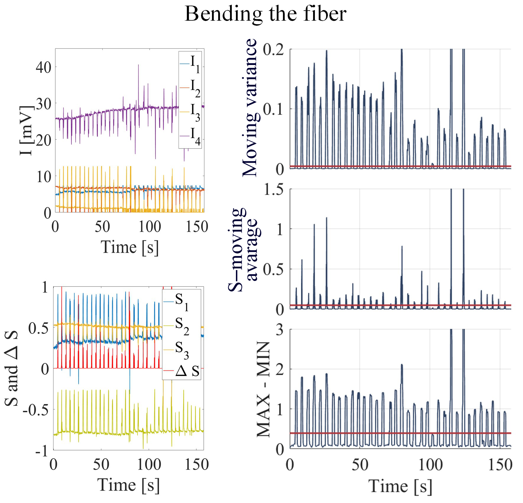
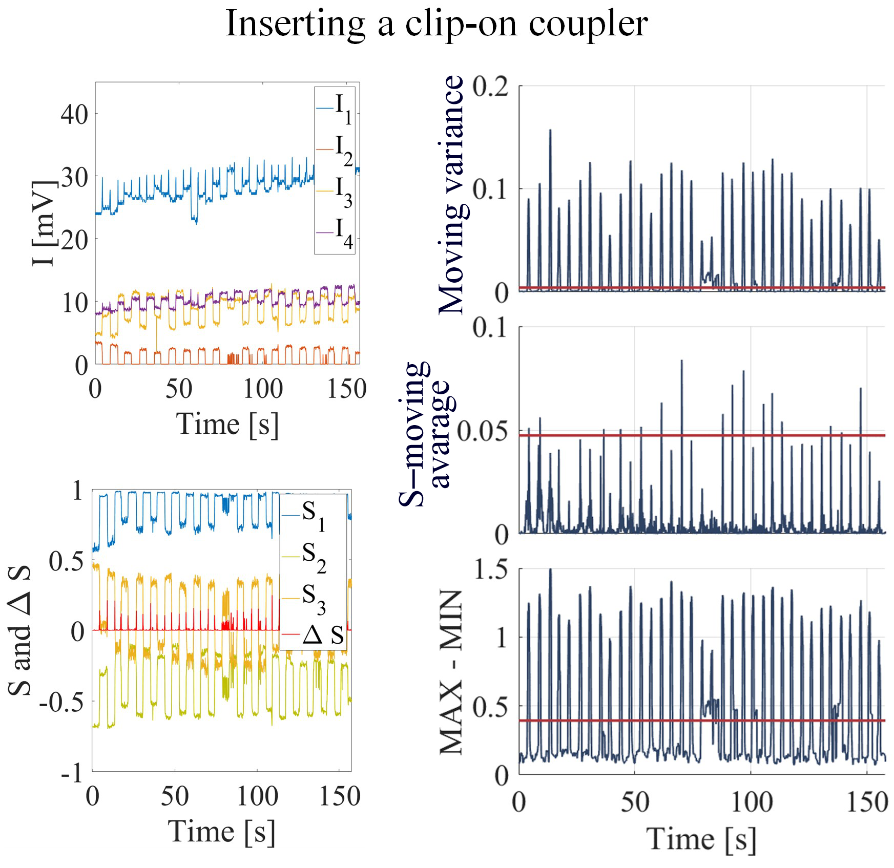
Table 2 includes the calculated efficiencies of disturb-ance detection for each parameter for touching, bending, and clip-on coupler installation. The detection depends on the force and rapidity of the disturbance; hence, the efficiency of detection for touching is generally smaller.
Table 2.
The estimated effectiveness of disturbance detection for the FCSP implemented into QKD system for touching, bending and connecting a clip-on coupler.
Indicators |
Touching |
Bending |
Clip-on |
Moving variance |
60.0% |
100% |
100% |
S–moving average |
57.1% |
97.1% |
44.4% |
MAX-MIN |
48.6% |
97.1% |
100% |
Overall, for FCSP connected to the QKD system, the highest effectiveness demonstrates moving variance – for touching at 60%, for bending and clip-on at 100%.
Conclusions
This work presents the results of testing the FCSP system to monitor changes in the SOP of light pulses propagating in the fibre-based QKD system working with faint pulses. The applied sensor can enhance the security properties of the QKD setup with instantaneous response, which, as far as the authors are concerned, has not yet been presented.
Three time-dependent indicators were proposed to detect changes in SOP and may be used to define a violation of the system integrity by simple thresholding. As presented in the results part, the FCSP successfully performed as a fibre infringement sensor with high efficiency for intense disturbances like bending and inserting a clip-on coupler. Based on the results obtained, two indicators, moving variance and MAX-MIN, are recommended for further analysis.
Analysing faint-light pulses in the QKD setup is associated with a higher error of the calculated SOP, which leads to higher noise levels and lower detection efficiency. Despite this, the FCSP exhibits satisfactory sensor properties in the QKD system and introduces additional sensing features.
The necessity of analysing pulses propagating at a high rate in the QKD system is problematic due to the high costs of electronic processing systems. However, despite the faulty registration system, it is possible to detect fibre infringement with high effectiveness since optical fibre dis-turbances are longer than a period between measurements.
The fibre-optic link with a 900 μm jacket was examined through the tests. Since there were still polymer protecting layers, it can be concluded that disturbances will significantly influence the bare fibre.
In further work, algorithms insensitive to errors resulting from the low intensity of one intensity component will be investigated and introduced. As for future development, the improvement of an acquisition system is planned and the use of a data register or the change in the detecting system is considered. Also, work is also underway to simplify the system. Since the information gathered from two channels is sufficient for infringement detection, removing two channels is also considered.
Authors’ statement
Research concept and design, E.P., M.Ż., A.P., and P.M.; collection and assembly of the data, E.P.; data analysis and interpretation, E.P.; writing the article, E.P.; critical revision of the article, E.P., M.Ż., A.P., and P.M.; final approval of the article, E.P., M.Ż., A.P., and P.M.;
Acknowledgements
This project has received funding from the research and innovation program of the National Center for Research and Development under a grant agreement of DOB SZAFIR/01/A/023/01/2020.
References
-
Bernstein, D. & Lange, T. Post-quantum cryptography. Nature 549, 188–194 (2017). https://doi.org/10.1038/nature23461
-
Kumar, M. & Pattnaik, P. Post Quantum Cryptography(PQC) – An overview. (Invited Paper). in 2020 IEEE High Performance Extreme Computing Conference (HPEC) 1–9 (IEEE, 2020). https://doi.org/10.1109/HPEC43674.2020.9286147
-
Kuo, Y.-M., Garcia-Herrero, F., Ruano, O. & Maestro, J. A. RISC- V galois field ISA extension for non-binary error-correction codes and classical and post-quantum cryptography. IEEE Trans. Comput. 72, 682–692 (2022). https://doi.org/10.1109/TC.2022.3174587
-
Zapatero, V., Navarrete, A. & Curty, M. Implementation security in quantum key distribution. Adv. Quantum Technol. 2024, 2300380 (2024). https://doi.org/10.1002/qute.202300380
-
Mayers, D. Unconditional security in quantum cryptography. J. ACM 48, 351–406 (2001). https://doi.org/10.48550/arXiv.quant-ph/9802025
-
Scarani, V. et al. The security of practical quantum key distribution. Rev. Mod. Physics 81, 1301 (2009). https://doi.org/10.1103/RevModPhys.81.1301
-
Diamanti, E., Lo, H.-K., Qi, B. & Yuan, X. Practical challenges in quantum key distribution. npj Quantum Inf. 2, 16025 (2016). https://doi.org/10.1038/npjqi.2016.25
-
Bennett, C. H. & Brassard, G. Quantum cryptography: Public key distribution and coin tossing. Theor. Comput. Sci. 560, 7–11 (2014). https://doi.org/10.1016/j.tcs.2014.05.025
-
Bennett, C. H. Quantum cryptography using any two nonorthogonal states. Phys. Rev. Lett. 68, 3121 (1992). https://doi.org/10.1103/PhysRevLett.68.3121
-
Bruβ, D. Optimal eavesdropping in quantum cryptography with six states. Phys. Rev. Lett. 81, 3018 (1998). https://doi.org/10.1103/PhysRevLett.81.3018
-
Woo, M. K. et al. Plug-and-play QKD architecture with a self- optical pulse train generator. Opt. Express 30, 29461–29471 (2022). https://doi.org/10.1364/OE.463283
-
DQuantique. https://www.idquantique.com/quantum-safe-security/products/#quantum_key_distribution (Accessed: 23th May 2024)
-
Toshiba Digital Solutions Corporation. https://www.global.toshiba/ww/products-solutions/security-ict/qkd/products.html#4 (Accessed: 23th May 2024)
-
Nicholson, G. & Temple, D. J. Polarization fluctuation measure- ments on installed single-mode optical fiber cables. J. Light.Technol. 7, 1197–1200 (1989). https://doi.org/10.1109/50.32382
-
Ding, Y. et al. Polarization variations in installed fibers and their influence on quantum key distribution systems. Opt. Express 25, 27923–27936 (2017). https://doi.org/10.1364/OE.25.027923
-
Ramos, M. F., Silva, N. A., Muga, N. J. & Pinto, A. N. Full polarization random drift compensation method for quantum communication. Opt. Express 30, 6907–6920 (2022). https://doi.org/10.1364/OE.445228
-
Zhao, H. et al. Continuous-variable quantum key distribution robust against environmental disturbances. Opt. Express 32, 7783–7799 (2024). https://doi.org/10.1364/OE.510392
-
MacDonald, G. G. Detecting Eavesdropping Activity in Fiber Optic Networks. (The University of Oklahoma, 2012).
-
Chen, Y., Fu, Y., Xiong, J. & Wang, Z. Distributed fiber birefrin- gence measurement using pulse-compression -OTDR. Photonic Sens. 11, 401–410 (2021). https://doi.org/10.1007/s13320-020-0604-3
-
Su, Y., Zhang, C., Xu, Z. & Wang, Y. The Pressure Sensing Method Based on Polarization Properties in Fiber. in IEEE 2021 13th International Conference on Advanced Infocomm Technology ICAIT 9–15 (IEEE, 2021). https://doi.org/10.1109/ICAIT52638.2021.9702021
-
Su, Y., Zhou, H., Wang, Y. & Shen, H. A novel polarization demodulation method using polarization beam splitter (PBS) for dynamic pressure sensor. Opt. Fiber Technol. 41, 69–73 (2018). https://doi.org/10.1016/j.yofte.2017.12.015
-
Huang, Z., Wu, C. & Wang, Z. Stress direction measurement based on polarization state in optical fibers using the quaternion method. IEEE Photonics J. 9, 1–11 (2017). https://doi.org/10.1109/JPHOT.2017.2764102
-
Tan, S. J., Tiu, Z. C., Cheng, X. S. & Ahmad, H. All Fiber Temperature Sensor Based on TMD Alloy Coated Tapered Fiber. in 2020 IEEE 8th International Conference on Photonics (ICP), 89–90 (2020). https://doi.org/10.1109/ICP46580.2020.9206484
-
El Hajj, R., MacDonald, G., Verma, P. & Huck, R. Implementing and testing a fiber-optic polarization-based intrusion detection system. Opt. Eng. 54, 096107 (2015). https://doi.org/10.1117/1.OE.54.9.096107
-
Rashleigh, S. C. Origins and control of polarization effects in single- mode fibers. J. Light. Technol. 1, 312–331 (1983). https://doi.org/10.1109/JLT.1983.1072121
-
Iqbal, M. Z., Fathallah, H. & Belhadj, N. Optical Fiber Tapping: Methods and Precautions. in 8th International Conference on High- Capacity Optical Networks and Emerging Technologies 164–168 (IEEE, 2011). https://doi.org/10.1109/HONET.2011.6149809
-
Shibata, S., Hagen, N., Kawabata, S. & Otani, Y. Compact and high- speed Stokes polarimeter using three-way polarization-preserving beam splitters. Appl. Opt. 58, 5644–5649 (2019). https://doi.org/10.1364/AO.58.005644
-
Gamiz, V. L. Performance of a four-channel polarimeter with low- light-level detection. Proc. SPIE 3121, Polarization: Measurement, Analysis, and Remote Sensing (1997). https://doi.org/10.1117/12.283869
-
Negara, C., Beyerer, J. & Langle T. Simplified Stokes polarimeter based on division-of-amplitude. Proc. SPIE 11144, 111441B (2019). https://doi.org/10.1117/12.2532399
-
Goldberg, A. Z. et al. Quantum concepts in optical polarization. OSA13, 1–59 (2020). https://doi.org/10.1364/AOP.404175
-
Zhu, Q. et al. Autonomic end-to-end quality-of-service assurance over QKD-secured optical networks. Opt. Express 32, 18317–18333 (2024). https://doi.org/10.1364/OE.516443
-
Goldstein, D. Polarized Light, Revised and Expanded, 2nd Edition.(Boca Raton, 2003). https://doi.org/10.1201/9780203911587
-
Peinado, A., Lizana, A., Vidal, J., Iemmi, C. & Campos, J. Optimization and performance criteria of a Stokes polarimeter based on two variable retarders. Opt. Express 18, 9815–9830 (2010). https://doi.org/10.1364/OE.18.009815
-
Sun, S. H., Jiang, M. S. & Liang, L. M. Passive Faraday mirror attack in practical two-way quantum key distribution system. Phys. Rev. A 83, 062331 (2011). https://doi.org/10.48550/arXiv.1203.0739
-
Takesue, H., Honjo, T., Tamaki, K. & Tokura, Y. Differential phase shift-quantum key distribution IEEE Commun. Mag. 47, 102–106 (2009). https://doi.org/10.1109/MCOM.2009.4939284
-
Azzam, R. M. A. Poincaré sphere representation of the fixed- polarizer rotating-retarder optical system. J. Opt. Soc. Am. A 17, 2105–2107 (2000). https://doi.org/10.1364/JOSAA.17.002105