Optical frequency combs (OFCs) have transformed metrology, optical communications, and
high-precision spectroscopic applications. OFC technology has advanced quickly over the last
20 years, placing it at the forefront of optical engineering and laser research. High-quality and
stable OFCs are produced using sophisticated modulation techniques that effectively mould
the comb spectral properties. Four important modulation strategies for OFC generation are
compared in this study: Mach-Zehnder modulation (MZM), frequency modulation (FM),
phase modulation (PM), and polarisation modulation (PolM). Two important factors of OFC
namely, comb flatness and the number of lines generated are used to assess these modulators
performance. The results of experiments and simulations show the benefits and drawbacks of
each method and offer guidance on their optimal use in various optical systems. The results of
this study provide a detailed understanding of the optimisation of OFC generation, which will
aid in the creation of next-generation optical communication and sensor systems. Also, the
various applications of OFC are discussed in the last section of this study.
Introduction
Specialised lasers known as optical frequency combs (OFCs)
act as a kind of light ruler. They swiftly and precisely measure
precise light frequencies, ranging from visible red, yellow,
green, and blue light to invisible infrared and ultraviolet
light. Scientists can measure and manipulate light waves as
if they were radio waves using OFCs. Clocks, computers,
and other devices that use radio or microwave frequencies
can now be easily connected to optical waves that oscillate
at frequencies 10 000 times higher.
OFCs provide a degree of precision higher than any other
measurement method by directly measuring the oscillations
of light. Direct measurement characteristics is used in applications
ranging from quantum computation to metrology [1]
and the market and number of OFC manufacturing companies
are growing, as is the user community. The technique
known as OFCs finds use in many different fields, mainly
because of its accurate and reliable frequency references.
In domains such as atomic and molecular spectroscopy [2],
OFCs provide highly precise frequency references that allow
for reliable measurements. Applications like finding fundamental
constants and deepening our knowledge of quantum
systems depend on this technique. Timekeeping has been
revolutionised using OFCs [3]. They make it possible to produce
extremely steady optical frequencies, which are useful
for making extremely precise optical clocks. These optical
clocks are more accurate than conventional microwave frequency
atomic clocks [4]. High-resolution spectroscopy is
made possible by OFCs, which offer a dense collection of
regularly spaced frequency lines.
OFCs make it easier to precisely identify molecular
species using spectroscopic techniques in domains such as
biology and chemistry. This has applications in material
characterisation, medical diagnostics, and environmental
monitoring. Frequency combs can be used for coherent
communication in optical communication systems [5].They
make it possible to create several wavelength channels,
which facilitates the efficient use of the optical spectrum
and high-capacity data transmission [6]. In communication
networks [7], OFCs can be used to establish precise time
references, which will improve synchronisation and boost
data transmission efficiency overall.
Ultra-fast laser pulses [8] are produced by OFCs. Applications
for these pulses include materials processing,
attosecond physics, and non-linear optics. Broadband optical
spectra, such as those produced by frequency combs, are
useful for a number of purposes, such as material characterisation
and optical coherence tomography (OCT), a medical
imaging technique. Astronomical spectrographs [9, 10] use
OFCs to accurately characterise starlight. This aids in the
search for exoplanets and contributes to our understanding
of the universe. OFCs are helpful for space-based communication
[11, 12] search work has been done in the generation
of OFC.
Thus, OFCs have become invaluable tools with applications
in spectroscopy, quantum technologies, telecommunications,
and precision metrology. OFCs act as a foundation
that unites several scientific and technical fields. This
study focuses on the four important modulation strategies of
OFC generation, namely Mach-Zehnder modulation (MZM),
phase modulation (PM), frequency modulation (FM), and
polarisation modulation (PolM), and a comparative analysis
is performed on the results generated using these methods.
Fundamental principles of OFCs
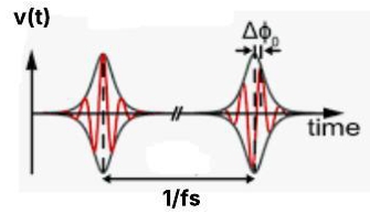
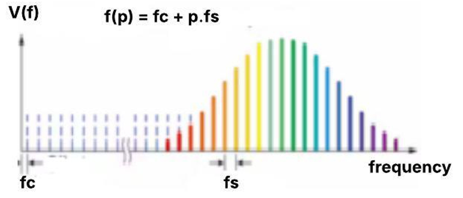
OFCs act as exact rulers in the optical frequency domain
as shown in Fig. 1. These are produced by specialised
laser [13] and are vital instruments in many high-precision
fields, including metrology, spectroscopy, and telecommunications.
A laser [14] typically has a natural bandwidth that is
influenced by the optical cavity and gain medium rather than
just one wavelength or frequency. The light waves in the
optical cavity will interfere with one another both destructively
and constructively, forming a configuration of standing
waves. Longitudinal modes are the distinct frequency sets
that characterise standing waves, as shown in Fig. 2. The
only frequencies of light that the resonant cavity permits to
oscillate independently are these modes.
The output of a laser has several thousands of modes.
As a result, the output intensity will always remain the
same; this is referred to as a continuous wave (CW). A CW
laser will periodically interfere with itself if all of its modes
are fixed in phase relationship. Consequently, the laser
generates light pulse trains and is referred to as mode-locking
technology [15] . Through the fixing of the relative phases
of each longitudinal lasing mode, mode-locked lasers [16]
produce ultra-short optical pulse trains that are repeated over
time [17, 18]. The time interval 𝜏𝑐 between these pulses is
provided by (1) [19]:
\(
f_s=\frac{2 L}{v}
\) (1)
where 𝐿 is the length of the cavity and 𝑣 is the speed of
light in vacuum. In the frequency domain, OFC is seen as
a pulse of equally spaced lines with the optical frequency at
its center given by (2) [20]:
\(
f(p)=f_c+p \cdot f_s
\) (2)
where p denotes the integer, 𝑓𝑠 is the comb spacing and 𝑓𝑐
is the carrier frequency. Early attempts to construct such
OFCs were based on heavily driven electro-optic (EO) mod-ulators [21, 22], which may impose thousands of sidebands
on a single-frequency input beam from a single-frequency
CW laser.
Experimental techniques for OFC generation
OFC creation provides a way to increase data speeds and
spectral efficiency. To produce OFCs, several experimental
methods have been devised; each has special benefits and
uses. Various general methodologies used to create OFCs are
tabulated in Table 1, which briefly describes the methodology
involved in each type with examples, their advantages and
disadvantages.
Uses stimulated Raman or Brillouin scatter-ing to generate frequency combs
Advantages
Can be generated in standard fibres
Disadvantages
Lower efficiency compared to Kerr combs
Although every method presents specific benefits—like
increased efficiency, broad bandwidth, compactness, or
adaptability—it also comes with its own set of disadvantages,
including complexity, low efficiency, or limited bandwidth.
Overall, Table 1 provides a comparative overview of the
different methods for generating OFCs, which are crucial
for applications in spectroscopy, precision metrology, and
advanced communication systems. The following sections
concentrate on OFC generation using different configurations
implementing MZM, FM, PM, and PolM
Generation of OFC using Mach-Zehnder modulator
(MZM)
An apparatus that modifies the phase or intensity of an optical
wave by means of the EO effect [23] is called MZM [24].
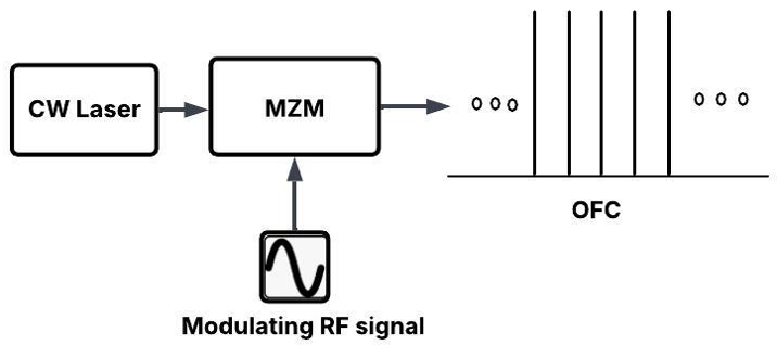
PM is introduced to an incoming optical signal when
it is driven by an electrical signal, as shown in Fig. 3.
Sidebands surrounding the carrier frequency can be produced
by adjusting the modulation settings [31]. MZM is an EO
modulator in which the modulator arms refractive index
varies in response to changes in the applied electric field.
It consists of two waveguides that act as interferometer
arms. The input waveguide, to which the laser is attached,
is split into two channels, each of which has electrodes
surrounding it. Because of the shift in refractive index
caused by the electrodes connection to the modulated signal
voltage and direct current (DC) bias voltage, each arm
refractive index is altered, resulting in PM. By connecting
the interferometer arms, the PM [32] is ultimately converted
to intensity modulation (IM). By adjusting the sidebands
power deviation, the IM non-linear effect [33] flattens the
comb lines at the MZM output. The electric field expression
of the input optical signal [34] is expressed in (3):
where 𝜔 is the frequency and 𝜙 is the phase of the input
signal. The output optical signal obtained at the output of
the modulator [34] is represented as (4):
represents the phase shift of the modulated signal, 𝜙initial
is the initial phase, and Δ𝜙c is the change in phase due to
modulation. This change in phase can be written as in terms
of electric field of modulating signal as:
where 𝑥 is the length of the EO material of width 𝑤, 𝑛r is
the non-linear refractive index and V is the electric field
generated around the EO material due to applied modulating
signal. By neglecting the constant phase term and applying
the identity, the output of modulated light wave becomes (5):
The function 𝐽𝑛 (𝑚) is defined as the n𝑡ℎ-order Bessel
function. The carrier with an amplitude of 𝐽0 (𝑚) and
a series of sidebands symmetrically spaced at frequency
separations of 𝜔𝑚, 2𝜔𝑚, 3𝜔𝑚, 4𝜔𝑚, etc. constitute the
spectrum. The Bessel function of first type and order n is
denoted by the function 𝐽𝑛 (𝑚). The Bessel function 𝐽𝑛 (𝑚)
determines the amplitude of the spectral components and is
shown in Fig. 4.
Fig. 4.OFC generation using dual electrode MZM
(DE-MZM).
OFC generation using dual electrode MZM
(DE-MZM)
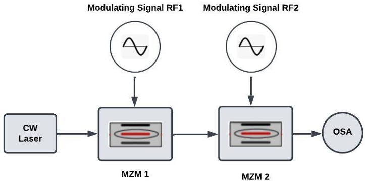
The cascaded structure of MZM [35] as shown in Fig. 5 increases the comb lines. Here, the two stages of DE-MZM
proposed by Kun generate 16 comb lines [36]. The first
stage generates 4 comb lines. When these comb lines [37]
act as carriers to the second stage, a total of 16 comb lines
are produced. Kun performed his analysis in Optisystem
software considering a wavelength of the CW laser to be
1552.52 nm of 10 dBm power and a line width of 100 kHz.
The half-wave voltage to the modulator is 3 V with an
extinction ratio of 20 dB [38]. The RF frequency of the
first modulator, MZM1 is taken as 16 GHz with 24.08 dBm
power and the RF frequency of second modulator, MZM2
is 4 GHz with 12.04 dBm power. With these specifications,
Kun was able to achieve 4 comb lines in the output of the
first MZM1 and 16 comb lines in the output of MZM2 with
the characteristic parameters stated in Table 2.
Characteristics of the output spectrum of stage 1 and 2.
Characteristics
Stage 1
Stage 2
RF (GHz)
16
4
Number of comb lines
4
16
Frequency spacing (GHz)
32
8
UMSR (dB)
16.5
16.5
Comb flatness (dB)
0.25
0.48
Here, the flatness of the frequency comb is maintained
when there is a drift in the bias voltage of MZM [39]. For
MZM1, the flatness is maintained at 0.53 dB for a bias drift
of ±4 %. The same performance is evident for a bias drift of
±10%. Taking into account MZM2, the flatness is maintained
at 0.54 dB for a bias drift of ±4%and also for a drift of ±10%.
When both MZMs are considered, the flatness is maintained
to be 0.48 dB for a bias drift of ±4%and 0.55 dB flatness and
15.9 dB unwanted modes suppression ratio (UMSR) [40,41]
for a bias drift of ±10% which is tabulated in Table 3.
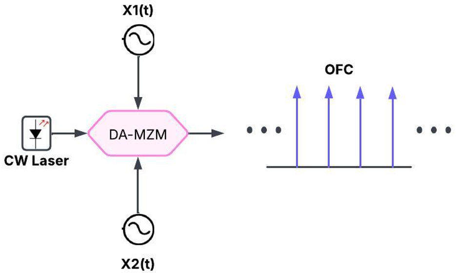
Hraghi et al. use a single DA-MZM [42] in his setup. DC
bias is applied to the DA-MZM. 𝑋1 (𝑡) and 𝑋2 (𝑡) are the
sinusoidal RF signals applied to MZM as shown in Fig. 6.
DC bias induces phase shift of 𝜃1 and 𝜃2 with 𝐴1 and 𝐴2
being the amplitude of 𝑋1 (𝑡) and 𝑋2 (𝑡), respectively. The
flatness condition of Sakamoto et al. [43] is used as in (6)
to (8):
Fig. 6.Optical flat comb generation based on DA-MZM.
\(
X_1(t)=A_1 \sin \omega_1 t
\) (6)
\(
X_2(t)=A_2 \sin \omega_2 t
\) (7)
\(
\Delta A \pm \Delta \theta=\pi / 2
\) (8)
where ΔA = (𝐴1 - 𝐴2)/2 is the peak to peak phase difference
Δ 𝜃 = (𝜃1 - 𝜃2)/2 is the DC bias difference of the two arms
of the modulators and 𝐴av = (𝐴1 + 𝐴2)/2 is the average
amplitude.
The output spectrum based on the above flatness condition
produces 11 comb lines with a comb flatness of 1.1 dB.
Generation of OFC using cascaded structure of two
dual arm (DA-MZM) and push pull MZM
It is a useful instrument in optical communication systems
due to its dual drive structure, which allows for fine control
over the generated comb lines. The dual drive MZM [44]
generates numerous comb lines by modulating the optical
carrier with two RF impulses.
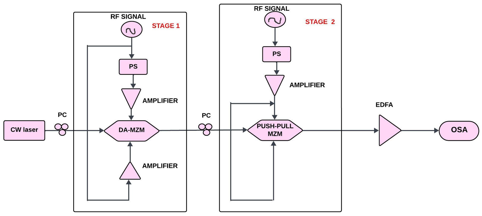
The setup implemented by Hraghi [42] consists of DAMZM
cascaded with push pull MZMs shown in Fig. 7 . Two
sine waves given in (6) and (7) are excited synchronously to
DA-MZM. The push pull MZM is excited by a sinusoidal
signal of 𝑆3 (𝑡) = A3 sin𝜔2𝑡. Assuming that the phase of the
source is zero, the output spectrum was obtained according
to (9) which is the expression of the n𝑡ℎ-order harmonic
envelope:
Here, Δ𝑅 is the allowed ripple, j is the spectrum region
that produces a flat response. By means of a linear
search, the different regions are found on the vector
C = [. . . ,𝐶𝑘,𝐶𝑘+1, . . . ]. Simulated annealing algorithm
is applied as an optimisation algorithm for the large search
space. The author proposed a new condition given in (11) to
generate flatness in the frequency comb [45]:
\(
\Delta A \pm \Delta \theta= \pm m \cdot \frac{\pi}{4}
\) (11)
In a single stage, MZM modulator is shown in Fig. 6. 4, 8,
16, and 32 new spectral lines are obtained with 𝑃 = 1 dB, in
addition to the center wavelength of 1552.52 nm.
In a two stage of MZM, 41 spectral lines are obtained
with 1 dB as comb flatness using the optimised algorithm
proposed in [46]. The modulation frequency is 12.5 GHz.
Generation of OFC using cascaded intensity and dual
parallel MZM (DP-MZM)
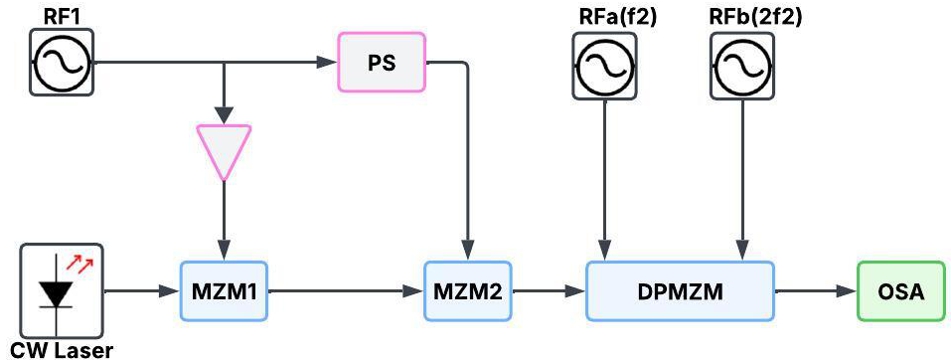
Zhou achieved 20 lines frequency comb using a structure
consisting of two intensity modulators cascaded with a
DP-MZM [47]. The comb lines generated are flat with
0.6 dB comb flatness. The first stage consists of 2 MZMs in
a cascade [48] fashion driven by an RF frequency f. The CW
laser [49] was modulated by one MZM. Keeping the DC bias
of MZM1 to zero, carrier and even sidebands are obtained
in the output spectrum. Then, when the bias of MZM2 is
set as 𝜋, it produces a double sideband with suppression
modulation. Two synchronised signals are applied to DPMZM
with frequency 𝑓2 applied to the upper arm and 2 𝑓2
applied to the lower arm shown in Fig. 8.
The modulation index is defined by (12):
\(
m=V_{R F} / V_\pi
\) (12)
Here, 𝑉𝑅𝐹 is the applied voltage and 𝑉𝜋 is the half-wave
voltage of the MZM. For MZM1, keeping 𝑚 = 1.55, 𝑓1 =
25 GHz, 4 spectral lines are obtained as the output of stage
1 with 0.2 dB comb flatness and frequency separation of
50 GHz. The other spectral lines are suppressed at 22 dB.
By proper bias adjustments to MZM, 20 OFC lines with
a comb flatness of 0.6 dB were achieved.
The number of comb lines can be increased by applying
more power of the applied RF signal to DP-MZM [50] and
also they can be increased by adding more modulators [51].
The other undesirable frequency sideband lines are present
in the output spectrum because of the limitations of the
extinction ratio present in the modulator [52]. Fig. 7.
Generation of OFC implementing only phase
modulations (PMs)
In [53], PMs in a cascade fashion were implemented to
obtain a higher modulation index, which in turn increased
the number of spectral lines compared to the use of electrical
amplifiers [54, 55]. The following sub-sections explain two
different structures with 2 and 3 PMs [56].
Generation of OFC using PMs in cascade fashion
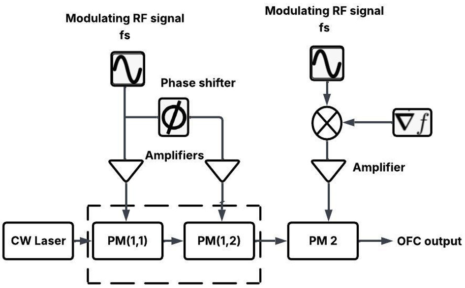
The system consists of two stage PM namely PM1 and
PM2. The first stage can be used with more than one PM.
A CW light wave is applied to the first stage of this structure.
A phase shifter is implemented in the first stage between the
modulators so that the driving signals are synchronous in Fig. 9.
When the phase difference 𝜙 is averaged, a flattened output
is obtained by adjusting the two parameters, the PM indices
𝑚1 and 𝑚2. The comb flatness becomes larger than 10 dB
when there is no frequency offset. The following results
are observed for the setup implemented with two PMs in
cascade:
Phase deviation has no impact on the flatness of the comb
Comb lines of 21 carriers are generated with less than
3 dB flatness.
To generate the flatness to be less than 3 dB, the frequency
offset is found to be higher than 1×10⁻⁵ 𝑓𝑠 . Then the output
of the frequency comb [47] is given by (13):
where 𝐽𝑛 is the first-order Bessel function and 𝑚 is the
modulation index [57]. Setting the frequency offset to zero,
the driving signal for the second stage PM2 is expressed as
in (14):
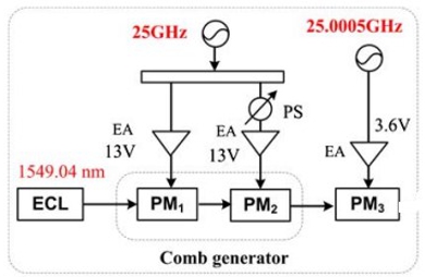
Experimental setup consists of 3 PMs [43] called PM1, PM2,
and PM3 shown in Fig. 10. These 3 stages are implemented
in 2 stages with 2 modulators in the first stage and 1 PM in
the last stage. They are driven by an RF frequency signal of
25 GHz frequency. The half-wave voltage of 4 V is amplified
to 13 V by an electrical amplifier. The insertion loss is set to
4 dB. The modulation index is found to be 3.25 in the first
stage. The number of frequency lines has been increased
by driving the second stage PM modulator with a frequency
offset of 500 kHz, the RF frequency being 25 000 GHz with
a peak voltage of 3.6 V. Here, the modulation is set to 0.45.
Thus, with the introduction of small frequency offset, 21
comb lines can be generated with comb flatness less than
3 dB.
The spectrum of the comb is produced after the first stage
of phase modulation without frequency offset. 19 comb
lines with a frequency spacing of 25 GHz are produced with
a flatness greater than 18 dB. At 25 GHz frequency spacing,
approximately 21 lines are produced. These OFCs have
a reduced flatness of less than 3 dB.
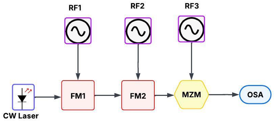
Generation of OFC using cascaded FM and MZM
Laser source is cascaded with a single-drive MZM and
2 FMs [59]. By adjusting or modifying the parameters of
an FM [60], the system can generate the desired OFC. RF
impulses with sinusoidal frequencies of 𝑓𝑚, 𝑓𝑚/2, and 2 𝑓𝑚,
respectively, power the modulators. As seen in Fig. 11, there
is no need for an amplifier or phase shifter because each of
the modulators receives the RF signal directly. As a result,
the design is straightforward, reliable, and power-efficient.
The following is a description of all the device specifications
mentioned in Table 4.
First set of RF1, RF2, and RF3 signals: 16 GHz, 8 GHz,
and 32 GHz
Second set of RF1, RF2, and RF3 signals: 8 GHz, 4 GHz
and 16 GHz.
The fundamental concept is to create sidebands that resemble
a comb-like spectrum by combining a PolM with a polariser
and PM effects. A PolM is a unique type of EOM that has
the ability to phase modulate two orthogonal polarisation
components at the same time. A bias voltage is not necessary
for a PolM to function, in contrast to a traditional PM
or intensity modulator (IM). Both input laser polarisation
components are modulated by the PolM [61]. Multiple
sidebands are produced by the PM effect that the RF signal
generates. The phase components interfere when they are
sent through a polariser, producing an output that is varied
in intensity. As a result, the OFC has an interval equal
to the frequency of the RF drive. Benefits include high
sideband generation efficiency, bias-free operation (no need
for DC bias), and adjustable comb spacing through RF
driving frequency adjustment. Unlike other non-linear comb
generation methods [62, 63], it is compact and stable.
OFC generation using PolM and frequency shifter
with double recirculating frequency shifting loops
APolM and a complementary frequency shifter are employed
in the two stage procedure described in the investigation to
create ultraflat and stable OFCs [64, 65].
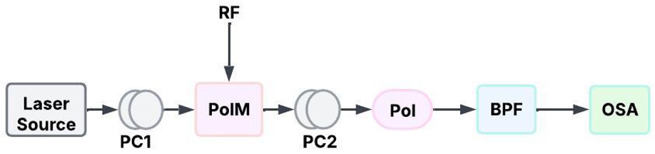
The first step is to use a PolM to create a five-carrier light
source. The ensuing frequency-shifting process is sparked
by this light source. The PolM [66] is driven by a radio
frequency component (RF1), two polarisation controllers
(PCs), a polariser (Pol), and an external cavity laser (ECL).
To produce the necessary polarisation states, the light from
the ECL is oriented at a particular angle to the PolM shown
in Fig. 12.
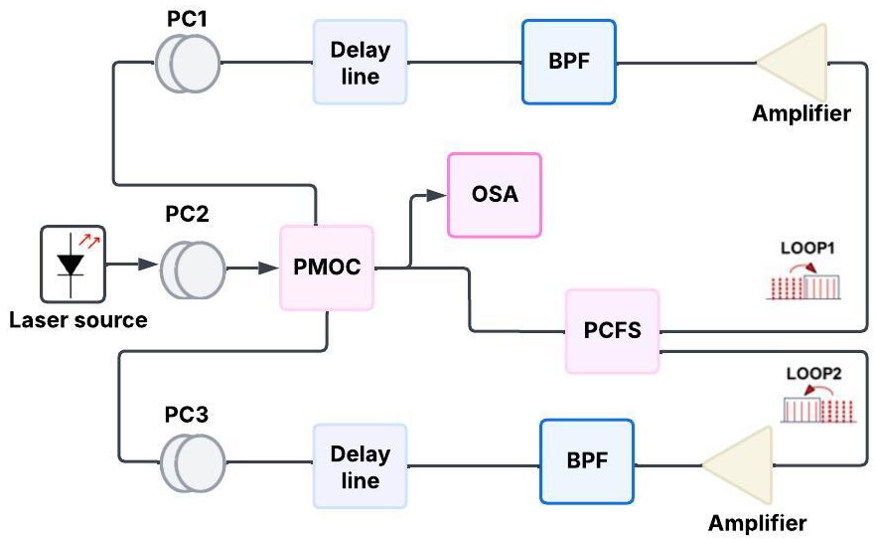
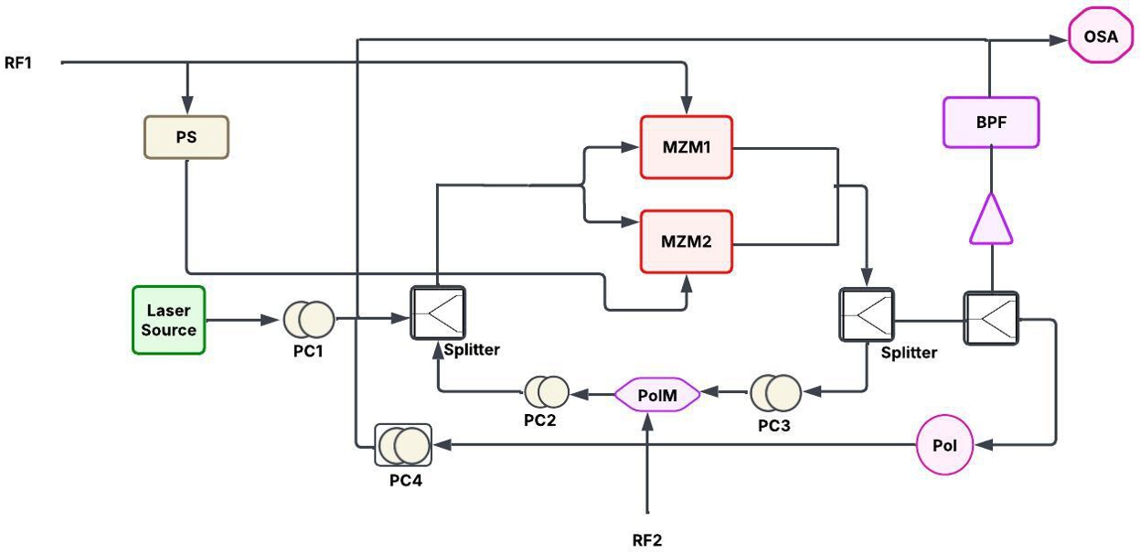
The polarisation-modulator-based complementary frequency
shifter (PCFS), which is intended to do frequency
shifting without the requirement for DC bias control, is then
fed the produced five-carrier light source. Compared to
traditional approaches, which usually require these controls,
this is a major improvement. By using a dual-recirculation
frequency shifter (RFS) arrangement [67] with polarisationmaintained
optical coupler (PMOC) [68] as shown in Fig. 13,
the PCFS makes it possible to generate numerous frequency
lines via a recirculating loop. To make sure that only the
desired frequency components are kept, light is amplified
and modulated before being filtered using an optical bandpass
filter (BPF). The approach places a strong emphasis on
optimising a number of factors, such as modulator drive voltage,
filter stop-band attenuation, and optical amplifier gain.
Fig. 13.Structure of dual-RFS arrangement with PMOC.
For the resulting OFC to be as flat and stable as possible,
several optimisations are essential. The trials demonstrated
the efficacy of the suggested method by demonstrating that
a high-quality OFC with hundreds of frequency lines and
minimum comb flatness below 2 dB could be created by
modifying these parameters.
To illustrate the effectiveness of the suggested OFC generating
strategy, the technique consists of both theoretical
simulations and experimental validations. The findings
demonstrate the method resilience with a tone-noise ratio
(TNR) of 38 dB and a frequency spacing of 12.5 GHz. This
thorough approach demonstrates the novel features of the
suggested system, which greatly improves OFC creation
while lowering complexity and noise.
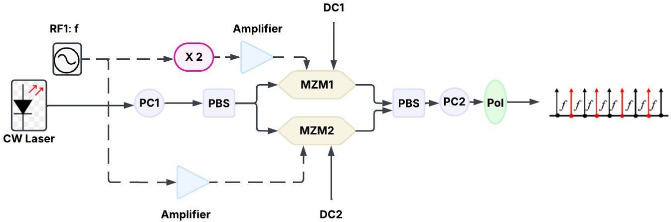
OFC generation using a polarisation division
multiplexing MZM (PDM-MZM)
The methodology for creating OFCs using a PDM-MZM is
shown in Fig. 14. The OFC is generated by a single PDMMZM
which in turn is made of 2 MZMs [69]. In contrast
to conventional techniques, which frequently require several
devices, this innovative method seeks to generate more comb
lines with higher spectral flatness. A CW laser source that
produces an optical carrier with a wavelength of 1550 nm
is part of the experimental setup. This light is introduced
into the PDM-MZM, which is made up of 2 sub-MZMs,
a polarisation beam combiner (PBC), and a polarisation
beam splitter (PBS). Complementary intensity modulation
along orthogonal polarisation directions is possible with the
PDM-MZM. RF impulses are applied to the sub-MZMs in
order to modulate the optical signal. The first sub-MZM RF
frequency is configured to produce the first comb lines, and
the second sub-MZM is powered by an RF signal that is either
one-ninth or nine times the first frequency, which enables
the creation of more comb lines. Another PDM-MZM is
cascaded as part of the process to further expand the number
of comb lines. The initial comb lines produced by the first
modulator can be enlarged through this cascading process,
yielding 81 comb lines with a spectral comb flatness of less
than 1.6 dB. In order to attain the required spectrum flatness
and stability, the methodology highlights the significance
of modifying a number of factors, including the modulator
modulation indices and DC bias points. The success of the
optimisation procedure was demonstrated by the testing findings,
which displayed a spectrum comb flatness of 0.63 dB
and an UMSR of 17.5 dB.
Polarisation-dependent high-quality OFC generator
based on RFS
The paper novel approach to creating a polarisation-dependent
OFC includes a number of crucial elements and procedures.
Using a DP-MZM [60] to perform carrier-suppressed
single sideband (CS-SSB) modulation forms the basis of
the suggested method implemented in Fig. 15. In order
to create the first frequency comb lines, this modulation
approach is essential. DP-MZM [70] can effectively manipulate
the optical signal since it operates in two orthogonal
polarisations [71].
To produce a five-line OFC, a polarisation modulator [65,
72] is incorporated into the system. By working with the
DP-MZM, the PolM makes it possible to use polarisation
multiplexing [73] to create numerous frequency lines. This
two-pronged strategy improves the comb generating process
overall productivity and efficiency.
Fig. 15.Structure of the system model with polarisation modulator and MZM.
An RFS mechanism is incorporated into the process,
which is crucial to increase the number of frequency lines
generated. This method produces a wider and more stable
OFC output by recirculating and shifting the generated
frequency components. Simulation data are included in the
research to show how effective the suggested methodology is.
The simulations demonstrate the potential for high-quality
comb creation by showing that the technique can produce
a 120-line OFC with a flatness of 3.91 dB. The outcomes
demonstrate how well the method works to produce a flat and
steady frequency comb. The technique has a strong emphasis
on optimising a number of factors, including the alignment of
the optical components and the modulation depth. Achieving
the intended performance criteria, such as output power
stability and spectral flatness, depends on these optimisations.
This thorough process demonstrates the creative features of
the suggested OFC generating approach, which uses cuttingedge
modulation methods and polarisation control to provide
excellent outcomes.
OFC generation using CMOS-compatible cascaded
MZM
This process creates OFCs with excellent tunability and
integration potential by using MZMs EOM capabilities [74].
Multiple comb lines with controlled spacing and amplitude
fluctuations can be generated using cascaded MZMs, making
it appropriate for a variety of applications, such as metrology
and optical communications [75]. Cascaded MZMs, which
are integrated on silicon-on-insulator (SOI) platforms, show
promise for small, on-chip solutions by producing dualwavelength
combs with 9 lines and 10 GHz spacing. In
silicon photonics, quasi-rectangular OFCs with 9 lines and
a comb spacing of up to 10 GHz can be created using two
cascaded EO MZMs while preserving amplitude variation
within 6.5 dB [76, 77].
The application of cascaded MZMs in silicon photonics
has been shown to produce quasi-rectangular OFCs with
certain properties [78]. The creation of OFCs with a high
degree of tunability in terms of central frequency and comb
spacing is made possible by the use of cascaded MZMs in
silicon photonics [76]. This is essential for a number of applications,
including metrology and optical communications.
With a comb spacing of up to 10 GHz and 9 lines, the exhibited
system can generate OFCs while keeping the amplitude
fluctuation within 6.5 dB. Using CMOS cascaded MZM,
the frequency spacing and output power with deviations
obtained are tabulated in Table 6
From detailed examinations of the different methods of OFC
generation done in the previous sections, the summary is tabulated
in Table 7. Two important features are targeted in
these generation methods: the number of comb lines generated
and the flatness in the power of the output spectrum [79].
Each design aims to increase the efficiency of the combs, but
maintaining flatness with an increased number of comb lines
remained difficult, but this problem was solved by increasing
the number of modulators in cascade fashion. A detailed
investigation of the Table 7 shows that with DE-MZM architecture, 16 comb lines are produced with power flatness as
good as 0.48 dB. Considering the structure with DP-MZM
and PolM, an increased number of comb lines of about
120 lines was generated but the power flatness is not that
desirable, which is of 3.91 dB. Similarly, other methods are
tabulated. Thus, a trade-off is to be made between these two
parameters.
Applications, challenges and future directions
of OFCs
This section highlights the milestones reached by researchers
in the field of OFCs over the past two decades. Table 8 shows the timeline of research achievements in this area. In
addition, OFCs can form a single source for WDM systems
that provides high data rates with low error rates required for
5G applications [80, 81]. Satellite networks are increasingly
using OFC technology to improve communication efficiency
and capacity. OFC integration is essential for contemporary
satellite communication systems because it enables highspeed
data transfer, flexible spectrum allocation, and improved
error correction. OFC greatly increases data capacity in satellite networks by enabling optical wireless communication
(OWC) systems that can reach bidirectional transmission
rates of up to 90 Gbps over 5000 km distances [82]. Optical
satellite networks architecture enables connections without
pre-deployed equipment and instantly adjusts to traffic volumes
and atmospheric conditions [83]. Researchers use
OFCs to effectively analyse human breath [84]. Current
available techniques for identifying minute amounts of chemicals
in breath are either unwieldy, slow, sensitive only to
particular molecules, incompetent in differentiating between
several compounds, or imprecise in determining their concentrations
[85]. The researchers were able to identify certain
molecules [86] and their quantities by identifying which
hues of light were absorbed and in what amounts—basically,
searching for light absorbed close to the "teeth" of the OFC.
With great precision, frequency resolution, and sensitivity,
researchers can evaluate a wide range of potential chemical
compounds simultaneously using the optical comb technique
[87]. But the approach is still in its early stages of
research only. From 1999, great interest has developed
towards the generation of OFC, the advancements are depicted
in Table 8. OFCs can identify particular molecules
as simple as carbon dioxide and complex antibodies. They
provide results with exceptional accuracy. OFCs can also
be used to detect COVID in the breath [88]. Researchers at
the University of Colorado, Toptica Photonics AG, and the
National Institute of Standards and Technology (NIST) have
now created an OFC that can identify molecules in a sample
in a billionth of a second. In order to identify the colour
spectrum that a molecule absorbs, the researchers employed
the widely used dual-OFC arrangement [89], which consists
of two laser beams that cooperate. Most dual frequency
comb configurations use two femtosecond lasers [90] that
pulse twice as quickly as each other. Future nanometer-level
measurements of far-off satellites may be made possible
by this invention, and the team is also investigating the
potential benefits of its time-programmable OFC for other
comb sensing applications [91]. Molecular spectroscopy and
trace gas detection, combs for astronomy, optical frequency
division, WDM [92], quantum control, optical communications,
biophotonics, quantum information processing [93],
characterisation and time/frequency dissemination of optical
clocks, microwave photonics [94], etc. are the various
applications of the OFC.
Theodor Hänsch and John Hall were granted the Nobel Prize in Physics in recognition of their contributions to the advancement of laser-
based precision spectroscopy, which served as the foundation for OFCs.
2000-
2004
First type of OFCs with frequency stabilisation and mode-locked lasers.
2005
Creating an OFC in a microresonator.
2007
Albert Fert and Peter Grünberg were given the Nobel Prize in Physics for their discovery of enormous magnetoresistance, which aided in the development of magnetic sensors that are frequently employed with OFCs.
2008
Microcomb and fibre-based combs.
2009
OFC start to find application in metrology, telecommunication, and optical clocks.
2013
OFC integrated with photonic devices.
2015
Extension to new domains like environmental sensing, quantum computing, and astronomy.
2018
OFC in quantum communication systems.
2021
On-chip OFC integration with silicon photonics.
Conclusions
This study compares Mach-Zehnder, frequency, phase, and
polarisation modulators for OFC creation, emphasising their
individual benefits and drawbacks. The findings showthat every
modulation method has different properties with respect
to stability, power efficiency, comb flatness, and spectral
bandwidth. FM and PM improve spectral purity, PolM
allows more degrees of freedom for comb shaping, and
MZM provides high tunability. The particular application
requirements, such as broad coverage for optical communications
[95] or strong spectral coherence for metrology,
decide on the selection of the modulation scheme. The
performance of OFC-based systems can be greatly enhanced
by refining these modulation techniques, opening the door
to developments in next-generation photonic technologies,
precise measurement, and high-speed optical networks. The
integration of data from multiple studies highlights the critical
role OFCs play in improving a variety of technological
sectors as scientists continue to investigate new directions
and improve current methods.
In summary, this study provides an extensive resource
for researchers, engineers, and hobbyists on the subject by
compiling a plethora of information on the fabrication of
OFCs using various modulators. Future breakthroughs in
OFC technology will undoubtedly influence precise measurement
and optical communications, opening the door to
revolutionary advances in science and technology.
Authors’ statement
K. Jeyapiriya has done the conceptualisation, methodology,
investigation, and writing the original draft.
M. Baskaran has done supervision, writing the review, editing,
and validation. Both authors have read and approved
the final manuscript.
References
Caldwell, E. D., Sinclair, L. C., Newbury, N. R. & Deschenes, J.-D. The time-programmable frequency comb and its use in quantum-limited ranging. Nature 610, 667–673 (2022). https://doi.org/10.1038/s41586-022-05225-8.
Cruz, F. C. et al. Mid-infrared optical frequency combs based on difference frequency generation for molecular spectroscopy. Opt. Express 23, 26814–26824 (2015). https://doi.org/10.1364/OE.23.026814.
Yang, K. Y. et al. Multi-dimensional data transmission using inverse-designed silicon photonics and microcombs. Nat. Commun. 13, 7862 (2022). https://doi.org/10.1038/s41467-022-35446-4.
Fischer, J. K. et al. Beyond 100g-high-capacity transport technologies for next generation optical core networks. In 2012 Future Network & Mobile Summit (FutureNetw), 1–9 (IEEE, 2012).
Baskaran, M. & Kishanlal, M. S. M. A novel DWDM-based comb source for future optical network. J. Nonlinear Opt. Phys. Mater. 33, 2350054 (2024). https://doi.org/10.1142/S0218863523500546.
Sun, D. et al. 10-GHz ultrashort pulse and flat optical comb generation via a semiconductor mode-locked laser. SSRN 1–13 (2025). https://doi.org/10.2139/ssrn.5084520.
Blind, N., Coarer, E. L., Kern, P. & Gousset, S. Spectrographs for astrophotonics. Opt. Express 25, 27341–27369 (2017). https://doi.org/10.1364/OE.25.027341.
Endo, M., Sukegawa, T., Silva, A. & Kobayashi, Y. Subgigahertz-resolution table-top spectrograph calibrated with a 4-GHz optical frequency comb. J. Astron. Telesc. Instrum. Syst. 6, 020501 (2020). https://doi.org/10.1117/1.JATIS.6.2.020501.
Giunta, M. et al. Optical frequency combs for space applications. In 2016 Conference on Lasers and Electro-Optics (CLEO), 1–2 (IEEE, 2016). https://doi.org/10.1364/CLEO_SI.2016.STh4H.5.
Chen, Z. et al. Tunable optical frequency comb generated using periodic windows in a laser and its application for distance measurement. Sensors 23, 8872 (2023). https://doi.org/10.3390/s23218872.
Rosado, A. et al. Numerical and experimental analysis of optical frequency comb generation in gain-switched semiconductor lasers. IEEE J. Quantum Electron. 55, 1–12 (2019). https://doi.org/10.1109/JQE.2019.2943482.
Ye, J. & Cundiff, S. T. Femtosecond optical frequency comb: Principle, operation and applications (Springer Science & Business Media, 2005).
Sooudi, E. et al. Observation of harmonic-mode-locking in a mode-locked InAs/InP-based quantum-dash laser with CW optical injection. IEEE Photonics Technol. Lett. 23, 549–551 (2011). https://doi.org/10.1109/LPT.2011.2114338.
Jones, D. J. et al. Carrier-envelope phase control of femtosecond mode-locked lasers and direct optical frequency synthesis. Science 288, 635–639 (2000). https://doi.org/10.1126/science.288.5466.635.
Udem, T., Holzwarth, R. & Hänsch, T. W. Optical frequency metrology. Nature 416, 233–237 (2002). https://doi.org/10.1038/416233a.
Zhai, K., Wang, W., Zhu, S., Wen, H. & Zhu, N. Optical frequency comb generation based on optoelectronic oscillator and Fabry-Perot phase modulator. IEEE Photonics J. 15, 1–5 (2023). https://doi.org/10.1109/JPHOT.2023.3323286.
Buscaino, B., Zhang, M., Lončar, M. & Kahn, J. M. Design of efficient resonator-enhanced electro-optic frequency comb generators. J. Light. Technol. 38, 1400–1413 (2020). https://doi.org/10.1109/JLT.2020.2973884.
Parriaux, A., Hammani, K. & Millot, G. Electro-optic frequency combs. Adv. Opt. Photonics 12, 223–287 (2020). https://doi.org/10.1364/AOP.382052.
Qu, K. et al. Ultra-flat and broadband optical frequency comb generator via a single Mach–Zehnder modulator. IEEE Photonics Technol. Lett. 29, 255–258 (2016). https://doi.org/10.1109/LPT.2016.2640276.
Rosado, A. et al. Experimental study of optical frequency comb generation in gain-switched semiconductor lasers. Opt. Laser Technol. 108, 542–550 (2018). https://doi.org/10.1016/J.OPTLASTEC.2018.07.038.
Fan, Y. & Shore, K. A. Generation of optical frequency combs using gain switched semiconductor nanolasers. IEEE Photonics Technol. Lett. 35, 713–716 (2023). https://doi.org/10.1109/LPT.2023.3274164.
Imai, K., Kourogi, M. & Ohtsu, M. 30-THz span optical frequency comb generation by self-phase modulation in an optical fiber. IEEE J. Quantum Electron. 34, 54–60 (1998). https://doi.org/10.1109/3.655007.
Bassiouni, M., Ismail, T., Selmy, H. & Badr, Y. Generation of ofc by self-phase modulation and multiple laser sources in HNLF. In 2020 16th International Computer Engineering Conference (ICENCO), 203–206 (IEEE, 2020). https://doi.org/10.1109/ICENCO49778.2020.9357325.
Weng, H.-Z. et al. Optical frequency comb generation in highly nonlinear fiber with dual-mode square microlasers. IEEE Photonics J. 10, 7102009 (2017). https://doi.org/10.1109/JPHOT.2017.2780280.
Ho, K.-P. & Kahn, J. M. Optical frequency comb generator using phase modulation in amplified circulating loop. IEEE Photonics Technol. Lett. 5, 721–725 (1993). https://doi.org/10.1109/68.219723.
Ullah, S. et al. Ultra-wide and flattened optical frequency comb generation based on cascaded phase modulator and LiNbO3-MZM offering terahertz bandwidth. IEEE Access 8, 76692–76699 (2020). https://doi.org/10.1109/ACCESS.2020.2989678.
Verma, P. & Singh, S. Exploiting cross-polarization modulation in semiconductor optical amplifier-Mach-Zehnder interferometer for enhanced optical frequency comb generation. Opt. Eng. 63 (2024). https://doi.org/10.1117/1.oe.63.11.115101.
Yang, T., Dong, J., Liao, S., Huang, D. & Zhang, X. Comparison analysis of optical frequency comb generation with nonlinear effects in highly nonlinear fibers. Opt. Express 21, 8508–8520 (2013) https://doi.org/10.1364/OE.21.008508.
Khalil, M., Sun, H., Papatheodorakos, T., Adams, R. & Chen, L. R. Optical frequency comb generation using integrated cascaded mzms on soi. In 2024 Photonics North (PN), 1–2 (2024).
Zhang, S. et al. Generation of a flat optical frequency comb via a cascaded dual-parallelMach-Zehnder modulator and phase modulator without using the fundamental tone. Photonics 10, 1340 (2023). https://doi.org/10.3390/photonics10121340.
Qu, K., Zhao, S., Li, X., Tan, Q. & Zhu, Z. Ultraflat and broadband optical frequency comb generator based on cascaded two dual-electrode Mach–Zehnder modulators. Opt. Rev. 25, 264–270 (2018). https://doi.org/10.1007/s10043-018-0417-4.
Sakamoto, T., Kawanishi, T. & Izutsu, M. Widely wavelength-tunable ultra-flat frequency comb generation using conventional dual-drive Mach-Zehnder modulator. Electron. Lett. 43, 1 (2007). https://doi.org/10.1049/el:20071267.
Sun, H., Khalil, M., Wang, Z. & Chen, L. R. Recent progress in integrated electro-optic frequency comb generation. J. Semicond. 42, 041301 (2021). https://doi.org/10.1088/1674-4926/42/4/041301.
Nazneen, R. & Zahir, E. Analysis and optimization of an optical frequency comb for multiple channel transmission in a fiberoptic system. In 2016 3rd International Conference on Electrical Engineering and Information Communication Technology (ICEEICT), 1–4 (2016). https://doi.org/10.1109/CEEICT.2016.7873132.
Deng, Z. et al. Ultra-precise optical phase-locking approach for ultralow noise frequency comb generation. Opt. Laser Technol. 138, 106906 (2021). https://doi.org/10.1016/j.optlastec.2020.106906.
Hraghi, A., Chaibi, M. E., Menif, M. & Erasme, D. Demonstration of 16QAM-OFDM UDWDM transmission using a tunable optical flat comb source. J. Light. Technol. 35, 238–245 (2017). https://doi.org/10.1109/JLT.2016.2636442.
Sakamoto, T. & Chiba, A. Multiple-frequency-spaced flat optical comb generation using a multiple-parallel phase modulator. Opt. Lett. 42, 4462–4465 (2017). https://doi.org/10.1364/OL.42.004462.
Li, W., Wang, W. T., Sun, W. H., Wang, L. X. & Zhu, N. H.
Photonic generation of arbitrarily phase-modulated microwave signals based on a single DDMZM. Opt. Express 22, 7446–7457 (2014). https://doi.org/10.1364/OE.22.007446.
Sakamoto, T., Kawanishi, T. & Tsuchiya, M. 10 GHz, 2.4 ps pulse generation using a single-stage dual-drive Mach-Zehnder modulator. Opt. Lett. 33, 890–892 (2008). https://doi.org/10.1364/OL.33.000890.
Sakamoto, T., Kawanishi, T. & Izutsu, M. Optimization of electro-optic comb generation using conventional Mach-Zehnder modulator. In 2007 Interntional Topical Meeting on Microwave Photonics, 50–53 (IEEE, 2007). https://doi.org/10.1109/MWP.2007.4378133.
Zhou, X., Zheng, X., Wen, H., Zhang, H. & Zhou, B. Generation of broadband optical frequency comb with rectangular envelope using cascaded intensity and dual-parallel modulators. Opt. Commun. 313, 356–359 >(2014). https://doi.org/10.1016/j.optcom.2013.10.054.
Wu, R., Supradeepa, V., Long, C. M., Leaird, D. E. & Weiner, A. M. Generation of very flat optical frequency combs from continuous-wave lasers using cascaded intensity and phase modulators driven by tailored radio frequency waveforms. Opt. Lett. 35, 3234–3236 (2010). https://doi.org/10.1364/OL.35.003234.
Malinowski, M., Rao, A., Delfyett, P. & Fathpour, S. Optical frequency comb generation by pulsed pumping. APL Photonics 2, 066101 (2017). https://doi.org/10.1063/1.4983113.
Huancachoque, L. A., dos Santos, M. L., Pereira, A. I., Nascimento, D. V. & Bordonalli, A. C. Optical frequency comb generation by dual drive Mach-Zehnder modulator with algorithm-assisted efficient amplitude equalization. In 2019 SBMO/IEEE MTT-S International Microwave and Optoelectronics Conference (IMOC), 1–3 (IEEE, 2019). https://doi.org/10.1109/IMOC43827.2019.9317691.
Dou, Y., Zhang, H. & Yao, M. Generation of flat optical-frequency comb using cascaded intensity and phase modulators. IEEE Photonics Technol. Lett. 24, 727–729 (2012). https://doi.org/10.1109/LPT.2012.2187330.
Zhang, J. et al. Flattened comb generation using only phase modulators driven by fundamental frequency sinusoidal sources with small frequency offset. Opt. Lett. 38, 552–554 (2013). https://doi.org/10.1364/OL.38.000552.
Zhang, Y., Zhang, H. & Shu, C. Generation of optical frequency comb via cross-phase modulation in an SOI waveguide. In 2022 Optical Fiber Communications Conference and Exhibition (OFC), 1–3 (2022). https://doi.org/10.1364/OFC.2022.Tu3E.4.
Yan, J., Dong, H. & Wang, Y. Line-spacing-multiplied optical frequency comb generation using an electro-optic talbot laser and cross-phase modulation in a fiber. Photonics 11, 282 (2024). https://doi.org/10.3390/photonics11030282.
Supradeepa, V. R. & Weiner, A. M. Bandwidth scaling and spectral flatness enhancement of optical frequency combs from phase-modulated continuous-wave lasers using cascaded four-wave mixing. Opt. Lett. 37, 3066–3068 (2012). https://doi.org/10.1364/OL.37.003066.
Wang, M. & Yao, J. Tunable optical frequency comb generation based on an optoelectronic oscillator. IEEE Photonics Technol. Lett. 25, 2035–2038 (2013). https://doi.org/10.1109/LPT.2013.2280666.
Mohammadi, A. et al. High-repetition-rate electro-optic frequency combs using cascaded silicon phase modulators. Opt. Express 33, 23820–23834 (2025). https://doi.org/10.1364/OE.558298.
Ujjwal & Kumar, R. Optical frequency comb generator employing two cascaded frequency modulators and Mach-Zehnder modulator. Electronics 12, 2762 (2023). https://doi.org/10.3390/electronics12132762.
Cui, Y. et al. Flat optical frequency comb generation by using one DPMZM and superposed harmonics. Opt. Commun. 531, 129223 (2023). https://doi.10.1016/j.optcom.2022.129223.
Lv, X. & Li, D. High-quality optical frequency comb generation-based on polarization modulator with RF frequency multiplication circuit and intensity modulator. J. Opt. Commun. 43, 347–352 (2022). https://doi.org/10.1515/joc-2019-0003.
Ataie, V., Myslivets, E., Kuo, B. P.-P., Alic, N. & Radic, S. Spectrally equalized frequency comb generation in multistage parametric mixer with nonlinear pulse shaping. J. Light. Technol. 32, 840–846 (2014). https://doi.org/10.1109/JLT.2013.2287852.
Cui, Y., Li, R. & Wu, S. Flat optical frequency comb generation using polarization modulator and frequency shifter with double recirculating frequency shifting loops. Opt. Quantum Electron. 49, 338 (2017). https://doi.org/10.1007/S11082-017-1179-0.
Kageyama, T. & Hasegawa, T. Fast polarization control for optical frequency combs. Opt. Express 29, 38477–38487 (2021). https://doi.org/10.1364/OE.439346.
Verma, P. & Singh, S. An approach to generate
cross-polarization modulation-enabled optical frequency comb with enhanced spectral flatness in traveling-wave semiconductor optical amplifiers. J. Opt. 26, 105703 (2024). https://doi.org/10.1088/2040-8986/ad6f24.
Li, R., Wu, S., Ye, S. & Cui, Y. Very flat optical frequency comb generation based on polarization modulator and recirculation frequency shifter. J. Opt. Commun. 39, 7–12 (2017). https://doi.org/10.1515/joc-2016-0108.
Li, D., Wu, S., Liu, Y. & Guo, Y. Flat optical frequency comb generation based on a dual-parallel Mach–Zehnder modulator and a single recirculation frequency shift loop. Appl. Opt. 59, 1916–1923 (2020). https://doi.org/10.1364/AO.381880.
Shang, L., Li, Y. & Wu, F. Optical frequency comb generation using a polarization division multiplexing Mach–Zehnder modulator. J. Opt. 48, 60–64 (2019). https://doi.org/10.1007/S12596-019-00516-2.
Wang, X., Wei, Y., Gong, C., Liu, S. & Fan, D. Optical frequency comb generation based on DPMZM cascades FM, EAM and PolM. In 2021 IEEE 6th Optoelectronics Global Conference (OGC), 56–60 (IEEE, 2021). https://doi.org/10.1109/OGC52961.2021.9654330.
Lin, T. et al. Polarization-dependent high quality optical frequency comb generator based on recirculating frequency shift. In 2018 Asia Communications and Photonics Conference (ACP), 1–3 (Optica Publishing Group, 2018). https://doi.org/10.1109/ACP.2018.8596266.
Guo, Y., Liu, Y., Li, D. & Wu, S. Ultra-flat optical frequency comb generation based on a polarization modulator and a butterworth band-stop filter. Appl. Opt. 60, 5540–5546 (2021). https://doi.org/10.1364/AO.424836.
Doumbia, Y., Wolfersberger, D., Panajotov, K. & Sciamanna, M. Tailoring frequency combs through vcsel polarization dynamics. Opt. Express 29, 33976–33991 (2021). https://doi.org/10.1364/OE.432281.
Xu, M. & Cai, X. Advances in integrated ultra-wideband electro-optic modulators. Opt. Express 30, 7253–7274 (2022). https://doi.org/10.1364/OE.449022.
Paul, P. S., Sadia, M., Hossain, R., Muldrey, B. J. & Hasan, S. Design of a low-overhead random number generator using CMOS-based cascaded chaotic maps. In Proc. Great Lakes Symposium on VLSI, 109–114 (ACM, 2021). https://doi.org/10.1145/3453688.3461504.
Wang, Z. et al. Optical frequency comb generation using CMOS compatible cascaded Mach-Zehnder modulators. IEEE J. Quantum Electron. 55, 1––6 (2019). https://doi.org/10.1109/JQE.2019.2948152.
Wang, Z. et al. On-chip frequency comb generation using cascaded MZMs in SiP for microwave photonics applications. In 2019 International Topical Meeting on Microwave Photonics (MWP), 1–3 (IEEE, 2019). https://doi.org/10.1109/MWP.2019.8892022.
Lin, J., Sepehrian, H., Xu, Y.-L., Rusch, L. A. & Shi, W. Frequency comb generation using a CMOS compatible SiP DD-MZM for flexible networks. IEEE Photonics Technol. Lett. 30, 1495–1498 (2018). https://doi.org/10.1109/LPT.2018.2856767.
Sharma, V. & Singh, S. Progress in optical frequency comb generation techniques towards flexible optical communication network. J. Opt. 27, 043001 (2025). https://doi.org/10.1088/2040-8986/adb1f2.
Dhakad, B. et al. Design and analysis of 16 channel WDM-OFC system with minimum ber for 5G applications. In Third International Conference on Communication, Networks and Computing CNC 2022, 28–39 (Springer, 2023). https://doi.org/10.1007/978-3-031-43140-1_4.
Yan, X., Zou, X., Pan, W., Yan, L. & Azaña, J. Fully digital programmable optical frequency comb generation and application. Opt. Lett. 43, 283–286 (2018). https://doi.org/10.1364/OL.43.000283.
Arya, V., Kumari, M., Chauhan, R. & Sharma, N. Secure optical wireless satellite network based OWC-OCDM system with DDW code. In 2023 4th IEEE Global Conference for Advancement in Technology (GCAT), 1–5 (IEEE, 2023). https://doi.org/10.1109/gcat59970.2023.10353493.
Pan, R., Lin, G., Shi, Z., Zeng, Y. & Yang, X. The application of disturbance-observer-based control in breath pressure control of aviation electronic oxygen regulator. Energies 14, 5189 (2021). https://doi.org/10.3390/EN14165189.
Rehman, M. et al. RF sensing based breathing patterns detection leveraging USRP devices. Sensors 21, 3855 (2021). https:/doi.org/10.3390/S21113855.
Khabbaz, A., Lampin, J.-F., Hindle, F. & Mouret, G. Molecular spectroscopy with a THz frequency comb. In 2024 49th International Conference on Infrared, Millimeter, and Terahertz Waves (IRMMW-THz), 1–2 (IEEE, 2024). https:/doi.org/10.1109/irmmw-thz60956.2024.10697872
Sterczewski, L. A., Bagheri, M. & Benmerabet, N. Cavity-enhanced Vernier spectroscopy with a chip-scale mid-infrared frequency comb. ACS Photonics 9, 994–1001 (2022). https://doi.org/10.1021/acsphotonics.1c01849.
Thorpe, M. J., Balslev-Clausen, D., Kirchner, M. S. & Ye, J. Human breath analysis via cavity-enhanced optical frequency comb spectroscopy. Opt. Express 16, 2387 (2007). https://doi.org/10.1364/OE.16.002387.
Jerez, B., Martín-Mateos, P., Prior, E., de Dios, C. & Acedo, P. Dual optical frequency comb architecture with capabilities from visible to mid-infrared. Opt. Express 24, 14986–14994 (2016). https://doi/10.1364/OE.24.014986.
Hu, H. & Oxenløwe, L. K. Chip-based optical frequency combs for high-capacity optical communications. Nanophotonics 10, 1367–1385 (2021). https://doi.org/10.1515/nanoph-2020-0561.
Lu, H.-H., Weiner, A. M., Lougovski, P. & Lukens, J. M. Quantum information processing with frequency-comb qudits. IEEE Photonics Technol. Lett. 31, 1858–1861 (2019). https://doi.org/10.1109/LPT.2019.2942136.