We present the results of simplified polarimetric methods for detecting disturbances on a fibre-optic link in a quantum key distribution system. The proposed methods use a polarisation coupler and a single polariser as a polarisation-sensitive detection system. The effectiveness of the disturbance detection was considered in a plug-and-play quantum key distribution system with phase encoding. This paper compares the performance of two simplified methods for determining changes in the state of polarisation in response to three types of disturbances, including touching, bending, and inserting a clip-on coupler. Also, the results of an experiment involving the entire procedure of introducing eavesdropping into a telecommunications fibre-optic cable are presented. The results of the measurements indicate the subsequent steps when attacking a fibre-optic cable. This article shows that a simplified polarisation-sensitive sensor can be implemented into a quantum key distribution system to detect disturbances and eavesdropping attempts, as well as enhance the security of the system.
Introduction
In the era of global data exchange, information security has become one of the most significant challenges. Protecting the confidentiality and integrity of transmitted information is a crucial issue today. Widely used classical cryptography is often based on Rivest-Shamir-Adleman (RSA) algo-rithms [1], whose security relies on the mathematical complexity of one-way functions. With current technology, such a solution is secure; however, as demonstrated in [2, 3], the development of quantum technologies, particu-larly quantum computers, poses a threat to the security of currently used encryption algorithms. This is due to their computational power, which is far greater than that of today’s supercomputers [4].
That is why quantum cryptography, otherwise known as quantum key distribution (QKD), has developed a field of encryption whose security does not depend on mathemati-cal complexity but is based on the principles of quantum physics. Among other things, it uses the superposition principle, the Heisenberg’s indeterminacy principle, and the non-cloning theorem [5]. To build the quantum key, QKD uses random values generated with a true random number generator (TRNG), for example, a quantum random number generator (QRNG), whose security, or actual randomness, also derives from the principles of quantum physics [6, 7]. The most well-known QKD protocol is the BB84 protocol proposed by Bennett and Brassard in 1984 [8]. It was the first protocol that sparked the development of quantum cryptography. There are also systems and QKD protocols using the phenomenon of quantum entanglement [9, 10].
In QKD systems, a quantum key is established by transmitting quantum states (e.g., by encoding in the phase or polarisation of photons), which can be used to encode information after evaluating its security. Quantum cryptog-raphy, in theory, enables the detection of eavesdroppers through, for example, a quantum bit error rate (QBER) analysis, which is a significant advantage over classical cryptography. Currently, existing systems are built using fibre-optic technology, rather than free-space optics. Therefore, such fibre-based plug-and-play systems are being developed that can be implemented in existing telecommunication fibre-links and networks [11–13].
Physical QKD systems are characterised by imperfec-tions associated with non-ideal optical path elements. The security loopholes in the system can be related to imperfections in the source and detectors. The use of an attenuated light pulse source involves a threat of multipho-ton pulses. This creates the possibility of a photon number-splitting (PNS) attack [14]. Although the ability to carry out this attack is theoretical and beyond the current state of technology, attacks of this type pose a serious security threat. To counter them, developments in QKD protocols are being introduced, such as SARG04 [15], decoy states [16], differential phase shift (DPS) [17], or coherent one way (COW) [18]. However, this does not apply to systems operating on entangled photon sources. In such systems, the ideal countermeasure to detector side channels is a meas-urement-device-independent (MDI) QKD solution [19].
However, the systems currently being introduced and developed still tend to use pulsed sources. This is due to their availability and, above all, lower prices. Besides, systems using attenuated pulses have a higher key generation rate than those using entangled photon sources.
Therefore, the main objective of this work was to optimise a previously proposed polarimetric sensor solution – a four-channel Stokes polarimeter (FCSP) [20] to protect QKD systems based on weak light pulses. This work focuses on simplifying the previous solution and adapting it for the analysis of weak pulses in a fibre-optic system. The study evaluates whether the simplified polarimetric setup is suitable for investigating quantum channel disturbances in a QKD system. The proposed methods also rely on comparing over-time changes in the state of polarisation (SOP) of light pulses propagating through the QKD system using a polarisation beam splitter (PBS)‑based measurements [21]. Since some birefringence characterises a single-mode fibre (SMF) due to the inhomogeneity of the medium, the disturbance resulting from an attempt to tap into an optical fibre will be noticeable in the change in a SOP of the propagating pulses.
The birefringence of SMF is sensitive to changes in external conditions, particularly mechanical stress, vibration and changes in ambient temperature. Variations resulting from changing external conditions are slow, especially in buried fibre-optic cables [22, 23]. Thus, in
signal processing, they can be isolated from dynamicchanges resulting from disturbances introduced by theattacker [24, 25].
The proposed methods were tested in a two-way plug-and-play QKD system [11, 12], which, due to its operation,allowed the insertion of an eavesdropping sensor without introducing additional light into the system.
This article is organised as follows: section 2 describesthe QKD system used along with two simplified polari-metric sensors. Section 3 describes the methods employedin the study, showing how to identify the degraded SOPusing a polarisation coupler, how to determine SOP changerates, and how to define an alarm situation. Section 4presents the results of PBS measurements carried outfor three types of disturbances: touching, bending, andconnecting a clip-on coupler, as well as the results ofmeasuring the entire process of conducting an attack ona telecommunications fibre-optic cable. This section alsoincludes a discussion of the results obtained. The articleends with the conclusions in section 5.
Experimental setup
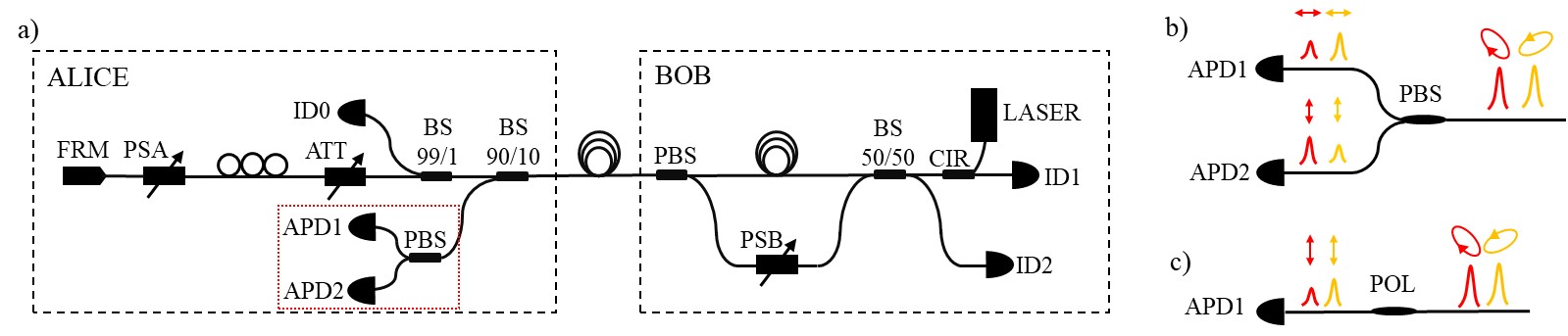
A polarisation-sensitive sensor is our proposedadditional protection solution for the quantum channel. Theprimary objective of the sensor is to measure changes in theSOP of pulses transmitted through a quantum channel. Weassume that sudden changes in this parameter are caused bya dynamic disruption of the optical fibre. We insert thesensor into the ALICE part, where a large portion (i.e.,90%) of the pulse intensity may be decoupled from thesensor. This is possible because the pulses are attenuatedtwice after the sensor is inserted. The sensor is marked witha red frame in Fig. 1(a). In this method, additional radiationis not introduced into the setup.
Fig. 1.(a) Experimental plug-and-play QKD setup, consisting of a sender (ALICE) and a receiver part (BOB). LASER – pulsed laser
source, ID1 and ID2 – single-photon detectors, CIR – fibre optical circulator, BS – fibre beam splitters with splitting ratio of 50/50,
90/10, and 99/1, PMA and PMB – phase modulator of ALICE and BOB, PBS – fibre polarisation beam splitter,
ID0 – monitoring photodiode, APD1 and APD2 – avalanche photodiodes, PC – polarisation controller, ATT – tunable intensity
attenuator, FRM – Faraday rotatory mirror; (b) two-channel polarisation-sensitive sensor with spatial multiplexing, PBS – fibre
polarisation beam splitter; (c) single-channel sensor with temporal multiplexing, POL – polariser
Fig. 1(b) presents the division of input pulses intoorthogonal polarisation components at the PBS coupler.The two input pulses are propagating in the QKD system,resulting from the time delay introduced in theinterferometer. Their SOPs are orthogonal to each other.Hence, on two avalanche photodiodes APD1 and APD2,complementary pairs of pulses can be observed.
The proposed polarisation-sensitive sensor method can consider one of the Stokes vector parameters as a polarisation parameter. The Stokes vector S consists of four parameters: S0 represents the total intensity, while S1, S2, and S3 indicate the relationships between the two orthogonal components: linear horizontal and vertical, linear diagonal and anti-diagonal, and circular right and left, respectively [26]. Since the PBS separates the radiation into linear horizontal and vertical components, we refer to such a method as spatial multiplexing. It can be used to determine the first two parameters of the Stokes vector: S0 and S1. Assuming the stability of S0, the S1 parameter can be used as an SOP indicator of the pulses. Both the first and the second pair of pulses can be used to determine the first Stokes parameter.
Another proposed solution is a single polarisation filter (POL) shown in Fig. 1(c). Such a solution is possible only because of the operation of the QKD system, in which two consecutive, orthogonally polarised pulses propagate. This method uses time multiplexing of initial pulses generated by the source. As it can be seen, such an arrangement corresponds to one of the arms of the PBS.
The amplitudes of pulses after PBS and POL are used to determine the change in polarisation state. The proposed solutions, unlike the previously described FCSP [20], allow the system to be encapsulated in fibre-optic technology. Since radiation does not have to be routed out of the fibre-optic cable, analysed and then detected, there are fewer losses. These systems are therefore more suitable for working with weak optical signals. The source used emits pulses with an average pulse duration time tFWHM = 100 ps and the estimated pulse power is 1.77 mW.
Methods
The amplitudes of the pulses after PBS and POL are used to determine the SOP change. As we mentioned earlier, the POL arrangement corresponds to one of the PBS arms. Therefore, to compare the effectiveness of these two methods, we used PBS both as a two-channel polarimeter [Fig. 1(b)] and as a polariser [Fig. 1(c)]. In this way, both methods were tested for the same impacts of disturbances.
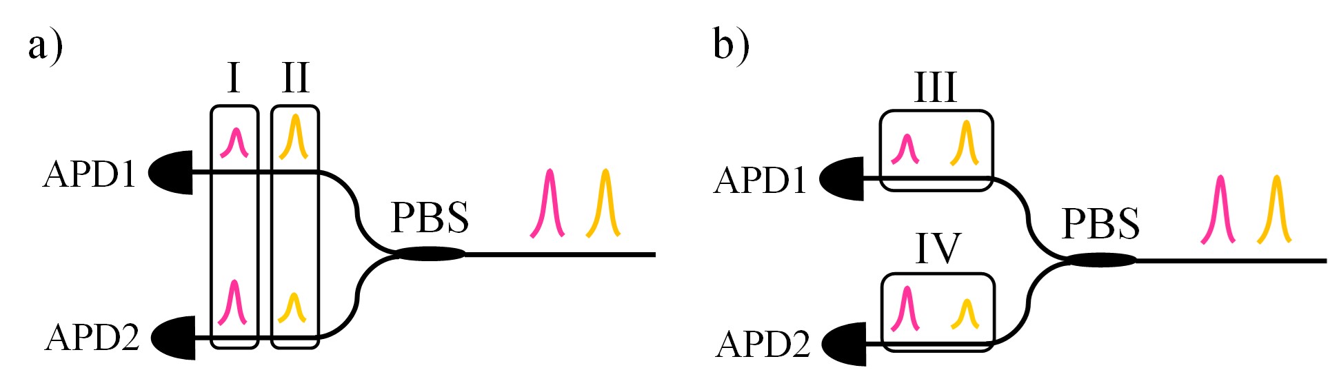
Fig. 2 shows possible pairs of pulses used to determine the first Stokes parameter. Fig. 2(a) corresponds to the PBS method, where either the I or II pair is measured. Simplification to the single polariser system is depicted in Fig. 2(b). Each arm, III and IV, corresponds to the polariser operation, with horizontal and vertical orientations, respectively.
Fig. 2.Possible combinations of pulse measurements to
determine the first Stokes parameter. (a) PBS method
with the division of pulses into polarisation state
components; (b) POL method – with filtering of one
polarisation state component from two consecutive
pulses.
The measurement methodology is as follows. First, detector signals for all pulses propagating through the PBS (PFC1550A ThorLabs) are measured. Maximum voltages measured by detectors for the following pulses are recorded using a PXI oscilloscope (PXIe-5185 National Instru-ments) synchronised with the arrival time of the pulses at the APD1 and APD2 (APD310 MenloSystems). Polarisation parameters are then determined according to the selected method and pulse combination. Two parameters were studied: I and V determined from the relations:
\(
I=I_1-I_2
\) (1)
\(
V=\frac{I_1-I_2}{I_1+I_2}
\) (2)
where I1 and I2 are the maximum voltages for measured pulses, corresponding to initial horizontal and vertical polarisation components, respectively.
The formula describing parameter V (2) corresponds to visibility and can be regarded as the second Stokes parameter S1. Determining this parameter, we do not include losses of both channels of the polarimeter because it did not affect the efficiency of the system but only complicated the calculation process. Parameter I (1) is a simplified form of the second Stokes parameter, which does not consider the change in total pulse intensity.
Based on polarisation parameters I and V, indicators of their change are calculated. These indicators remove the signals trends, allowing us to cut us off from slow changes and enhance the dynamic ones. Four indicators have been studied: Δa (3), MV(a) (4), MA(a) (5), and |a| (6). These were calculated both for I and V. To simplify, in the following formulas, the polarisation parameters I and V are denoted as a. Δa is the squared first difference of the polarisation parameter:
\(
\Delta a=\left(a_n-a_{n-1}\right)^2
\) (3)
where an and an−1 are the n-th and n−1-th measurement results, respectively. The MV indicator is a moving variance of the polarisation parameter and is designated based on the formula:
\(
M V(a)=V^2(a)=\frac{\sum_{n=1}^N\left(a_n-\bar{a}\right)^2}{N}
\) (4)
where a is the average value of the polarisation parameter from a set of N measurements, an is the n-th measurement result. The moving average indicator MA is calculated as:
\(
M A(a)=(a-S M A)^2
\) (5)
where SMA is the moving average of N most recent measurements. The |a| indicator as:
\(
|a|=\max _N a-\min _N a
\) (6)
for N most recent measurements.
Indicators of the SOP change are alarm indicators for detecting the presence of a fibre-optic disturbance.
Threshold levels are determined for the calculated alarm indicators based on the measurement of the undisturbed optical fibre. Exceeding the threshold levels by the alarm indicators signifies disruption of the optical fibre, which can result from an attempt to wiretap. Threshold levels were set at 110% of the maximum values that alarm indicators can reach without disturbances.
In this research, disturbances such as touching, bending, and pinning of a clip-on coupler were introduced on a 900 μm SMF test fibre during the experiment. During the fibre-optic attack, all such types of events are expected to occur. The disturbances introduced were not standardised. The objective was to determine only the binary information whether a disturbance was present or not, rather than to define its specific properties. Fibre bending was performed with a 1–4 cm bending diameter. The clip-on coupler (FOD 5503) is an actual device used to split the radiation from an optical fibre. To eavesdrop on the information, protective layers should be removed from the fibre. However, the experiment was conducted on a 900 μm optical fibre with polymeric layers to imitate the movement, due to its high brittleness without protection.
Further, the entire process of plugging in the wiretap on the indoor fibre-optic cable with two SMFs (ACE - TKF CTMC 2x SM G.657.A1, (1x2) A-DQ(ZN)9Y 74921 TKF) was carried out. During this experiment, all protective layers were removed, and the clip-on coupler was attached to a bare fibre. The cable consisted of the following elements: plastic cable jacket, strengthening fibres, inner plastic jacket, and two coated fibres.
Results and discussion
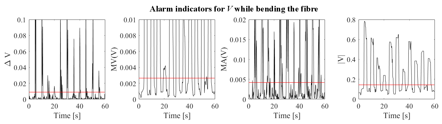
The PBS sensor was implemented in the QKD system. For over 10 min, the sensor response to events such as touching, bending, and pinning of the clip-on coupler was tested. Disturbances were introduced at an interval of 5 s. Example results are shown in Fig. 3. These are the temporal measurements of alarm indicators for parameter V during fibre bending, calculated for the first pulse (method I in Fig. 2). The red line indicates the adopted threshold levels. Different levels of indicator changes are due to different strengths of the inflicted disturbance.
Fig. 3.Alarm indicators ΔV, MV(V), MA(V), and |V| during optical fibre bending within 1 min. Red lines indicate threshold
levels for each indicator.
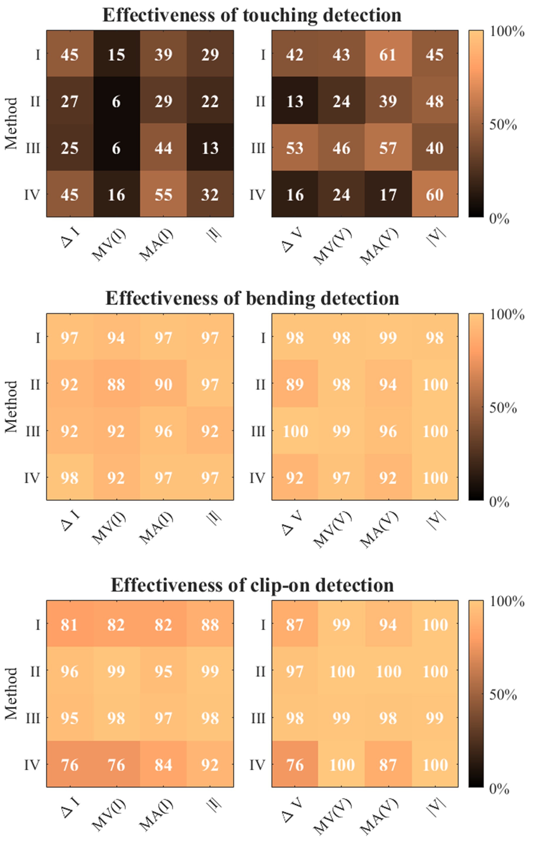
The effectiveness of each alarm indicator for every type of disturbance was calculated based on the results of exceeding the indicators over threshold levels, both for I and V. Effectiveness was determined as the ratio of detected alarm situations to the number of events. A summary of the results concerning effectiveness is presented in Fig. 4. Detection effectiveness depends on the intensity of the disturbance. Weak disturbances such as touching are characterised by low efficiency, with a maximum effectiveness of 61%. High-intensity perturbations such as bending an optical fibre and plugging in a clip-on coupler cause a significant change in birefringence, causing relatively dynamic changes in SOP, visibly distinguishable from noise. Bending and clip-on detection efficiency ranges from 76% to 100%, depending on the parameter considered. For most cases, relatively higher efficiency is observed for V, rather than the simplified I parameter. Based on the results obtained, it is not possible to clearly define which parameter is the most accurate. This probably requires further research, more samples, and long-term measurements in a real QKD system.
Fig. 4.Detection efficiencies determined for three types of
perturbation: touching, bending, and clip-on coupler
insertion. The alarm indicators Δa, MV(a), MA(a), |a|
were calculated for I and V for all four methods I, II, III,
and IV. The efficiencies presented are shown on
a percentage scale.
Next, an analogue measurement of SOP changes was carried out while performing the actual eavesdropping attempt. A telecom fibre-optic cable with two SMFs was used for the tests. Its construction consisted of two plastic jackets with strengthening fibres in between and two optical fibres with polymer layers. First, the plastic jackets were removed. Then, the protective coating was removed from one of the fibres, and a clip-on coupler was connected. Based on intensity measurements, alarm indicators were determined.
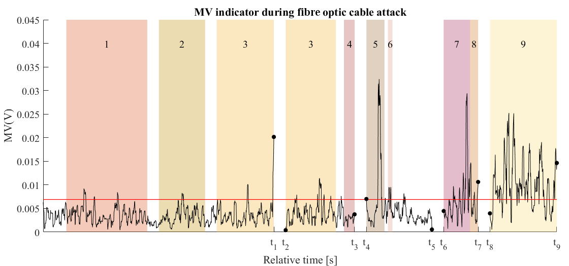
Fig. 5 shows representative results of the MV indicator, calculated for the V parameter. Due to the signal registration method used, buffer overrun and heating of the measurement device, the measurement was carried out in five stages, marked on the time axis: 0–t1 (200 s), t2–t3 (60 s), t4–t5 (60 s), t6–t7 (30 s), and t8–t9 (60 s). The dots on the graph indicate the final and initial measurement points in successive stages. A different threshold level for the presented situation is caused by the presence of an additional cable, resulting in higher noise levels. The individual time intervals for the following activities are marked on the chart with a coloured background and consecutive numbers: 1 – removing the jacket, 2 – cutting the aramid fibres, 3 – removing the inner jacket, 4 – fibre selection, 5 – removing the acrylic coating, 6 – cleaning, 7 – putting fibre on clip-on coupler, 8 – clip-on closing, and 9 – latching. Throughout the process of attacking the cable, there was touching and moving of the fibre-optic cable, which caused additional SOP changes, including when the activities were not marked.
Fig. 5.Disturbance detection during the introduction of eavesdropping on a fibre-optic cable based on the MV indicator results. The red
line indicates the threshold level. Subsequent events observed on the chart are highlighted with a coloured background: 1 – jacket
removal, 2 – cut of aramid fibres, 3 – plastic inner jacket removal, 4 – optical fibres selection, 5 – acrylic coating stripping, 6 –
cleaning with isopropanol, 7 – fibre manipulation, 8 – clip-on closure, 9 – clip-on latching. 0, ti – starting and ending times of the
following measurements. The limiting points are marked with black dots.
As can be observed in the diagram, an optical fibre without plastic protective layers is a stress-sensitive medium. The mere manipulation of the optical fibre to put it in a clip-on and squeeze it is qualified as an alarm situation. Once the clip-on is closed, a basically continuous alarm is observed. This is due to the signal decrease after it leaks from the optical fibre when the clip-on coupler is closed, and the fibre is tightened. These losses increase the effect of noise on the change in the alarm rate.
The operation of the sensor under consideration does not require additional light in the system. No effect of its presence in the system was observed on the level of QBER for the assumed initial pulse. The removal of part of the radiation using a coupler (BS 90/10) plays the same role as the optical attenuator ATT. Reducing the initial pulse power could require a coupler with a smaller split ratio, but one that allows sufficient power to be delivered to the APD detectors.
Conclusions
The presented solution builds upon the previously proposed FCSP [20]. The main advantage of this solution is its suitability for operation with weak pulses, due to its great simplification and lower optical losses. The setup remains in fibre-optic technology, and its construction is based solely on commercial components. Hence, the cost of manufacturing such a sensor is much lower. The simplifica-tion of the system enables faster analysis of the measured data, and the signal processing circuit is simplified.
The described system allows the detection of fibre-optic disturbances based on threshold alarm indicators. Detection efficiency for strong disturbances, such as optical fibre bending and clip-on, is high. It is also possible to implement more advanced methods of setting threshold levels for more efficient detection of disturbances and their distinction. System optimisation, both for calibration and disturbance classification, may require the use of machine learning. An AI model trained, based on long-term measurements of the undisturbed system and subjected to disturbances can enable an effective system operation.
However, at the preliminary research stage, it was not necessary. In addition, considering the level of attenuation that would be introduced in a QKD system, the implementation of our sensor solution does not introduce additional quantum errors. Moreover, in further work for signal analysis, the implementation of an analogue processing circuit is planned.
Authors’ statement
Research concept and design, E.P., M.Ż., A.P., P.M.; collection and assembly of the data, E.P.; data analysis and interpretation, E.P.; writing the article, E.P.; critical revision of the article, E.P., M.Ż., A.P., P.M.; final approval of the article, E.P., M.Ż., A.P., P.M.
Acknowledgements
This project has received funding from the National Center for Research and Development research and innovation program under grant agreement: DOB SZAFIR/01/A/023/01/2020
References
Rivest, R. L., Shamir, A. & Adleman, L. A method for obtaining digital signatures and public-key cryptosystems. Commun. ACM 21, 120–126 (1978). https://doi.org/10.1145/359340.359342
Yan, B. et al. Factoring integers with sublinear resources on a superconducting quantum processor. arXiv.2212.12372, 1–32 (2022). https://doi.org/10.48550/arXiv.2212.12372
Mannalath, V., Mishra, S. & Pathak, A. A comprehensive review of quantum random number generators: Concepts, classification and the origin of randomness. Quantum Inf. Process. 22, 439 (2023). https://doi.org/10.1007/s11128-023-04175-y
Dudek, M., Siudem, G., Kwaśnik, G., Żołnowski, W. & Życzkowski, M. T. Optical fibre-based quantum random number generator: Stochastic modelling and measurements. Sci. Rep. 15, 10849 (2025). https://doi.org/10.1038/s41598-025-95414-y
Bennett, C. H. & Brassard, G. Quantum cryptography: Public key distribution and coin tossing. Theor. Comput. Sci. 560, 7–11 (2014). https://doi.org/10.1016/j.tcs.2014.05.025
Ling, A., Peloso, M., Marcikic, I., Lamas-Linares, A. &Kurtsiefer, >C. Experimental E91 quantum key distribution. Proc. SPIE 6903, 69030U (2008). https://doi.org/10.1117/12.778556
Ahn, B. et al. Implementation of Plug & Play Quantum Key Distribution Protocol. in 2018 Tenth International Conference on Ubiquitous and Future Networks (ICUFN) 47–49 (2018). https://doi.org/10.1109/ICUFN.2018.8436633
Valivarthi, R., Etcheverry, S., Aldama, J., Zwiehoff, F. & Pruneri, V. Plug-and-play continuous-variable quantum key distribution for metropolitan networks. Opt. Express 28, 14547–14559 (2020). https://doi.org/10.1364/OE.391491
Dusek, M., Haderka, O. & Hendrych, M. Generalized beam-splitting attack in quantum cryptography with dim coherent states. Opt. Cummun. 169, 103–108 (1999) https://doi.org/10.1016/S0030-4018(99)00419-8
Scarani, V., Acin, A., Ribordy, G. & Gisin, N. Quantum cryptography protocols robust against photon number splitting attacks for weak laser pulse implementations. Phys. Rev. Lett. 92, 057901 (2004). https://doi.org/10.1103/PhysRevLett.92.057901
Pawlikowska, E. et al. Testing of four-channel Stokes polarimeter performance for intrusion detection in QKD systems. Opto-Electron. Rev. 33, 153182 (2025). https://doi.org/10.24425/opelre.2025.153182
Su, Y., Zhou, H., Wang, Y. & Shen, H. A novel polarization demodulation method using polarization beam splitter (PBS) for dynamic pressure sensor. Opt. Fibre Technol. 41, 69–73 (2018). https://doi.org/10.1016/j.yofte.2017.12.015
Nicholson, G. & Temple, D. J. Polarization fluctuation measurements on installed single-mode optical fibre cables. IEEE J. Light. Technol. 7, 1197–1200 (1989). https://doi.org/10.1109/50.32382
Ding, Y. et al. Polarization variations in installed fibres and their influence on quantum key distribution systems. Opt. Express 25, 27923–27936 (2017). https://doi.org/10.1364/OE.25.027923
El Hajj, R., MacDonald, G., Verma., P. & Huck, R. Implementing and testing a fibre-optic polarization-based intrusion detection system. Opt. Eng. 54, 096107 (2015). https://doi.org/10.1117/1.OE.54.9.096107
MacDonald, G. G. Detecting eavesdropping activity in fibre optic networks. (The University of Oklahoma, 2012).