Scientists involved in building quantum computers are currently facing many physical difficulties.
Creating qubits, manipulating them and reading their state requires a lot of experience.
This paper describes an optical laser system as a test platform for quantum-optical control that
enables effective manipulation of an emulated quantum bit. Importantly, it is a reproduction
of the system controlling the optical path in real ion traps. This solution makes it possible to
study the phenomena occurring in such systems and to learn about the wide range of problems
that a designer and an operator of quantum systems may encounter, even before they start
building them. The optical system presented in the article uses, among others, a 532 nm laser,
acousto-optic modulators (AOMs), ultrafast light detectors, and a programmable FPGA chip.
The entire optical system was then attached to the QUBIT emulator and thoroughly tested.
The article describes the design and operation of the proposed optical system and shows an
example of how to control it using a Python script.
Introduction
The modernworld is striving very hard to create a fully functional
quantum computer [1], which, as we know, operates
on completely different principles compared to a classical
computer. Unlike classical computers based on a set of bits,
a quantum computer works on the basis of a set of quantum
bits called qubits. A qubit is represented by a state vector
in a two-dimensional complex Hilbert space [2]. Qubits
differ from classical bits in the way they encode and process
information, offering capabilities that go beyond what
is possible with classical bits. The classic bit can take only
one of two discrete states: ’0’ or ’1’. The qubit, on the other
hand, is not limited to being in just one of the two basis
states, denoted |0⟩ and |1⟩. Instead, it can be described
by a general quantum state that combines these basis states
with certain complex-valued coefficients. Upon measurement,
the qubit yields one of the two outcomes - |0⟩ or |1⟩ -
with probabilities given by the squares of the magnitudes of
these coefficients, such that the total probability is always
equal to 1. We refer to such a combination of basis states
as a superposition. The qubit retains its quantum nature
until it is measured, at which point its state collapses to
one of the basis states, effectively behaving like a classical
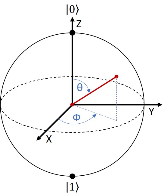
bit. In addition, a qubit is also characterised by a relative
phase between the components |0⟩ and |1⟩, which plays a
crucial role in the qubit evolution under the influence of the
Hamiltonian system [3]. The current state of the qubit, i.e.,
its phase and superposition, can be represented graphically
by two angles 𝜃 (THETA) and 𝜙 (PHI) on the Bloch sphere Fig. 1.
In real quantum systems, the values of these angles can
be set with appropriate and precise pulses of, for example,
laser light. In general, in many quantum systems, the formation
and application of laser pulses is a very important
way to control various internal quantum states [4–8]. By
choosing the power of the laser, its wavelength and duration
of the pulse, such a control system can be tuned and the
expected effects can be obtained. The practical usability
of such a solution then depends to a large extent on timing
and amplitude precision of the formation of the pulses
themselves, as well as the ability to deal with unpredictable
disturbances that may arise spontaneously. The importance
of laser stability and precise control of the optical pulses
was also discussed in more recent implementations of laser
qubit control systems [9, 10].
Building a quantum system with the potential to become
a quantum computer is not a simple undertaking. The
challenge of creating a suitable set of stable qubits is only
one of the difficulties that emerge. Another, perhaps even
bigger problem arises when we want to control individual
qubits. Unwanted quantum phenomena, internal noise
of the system, electromagnetic interference from the environment,
imperfection in the materials and components
used, improper procedures for forming control pulses, or
various types of operator errors – means we have to deal
with a whole avalanche of difficulties and issues related to
the stability of the system and the repeatability of the implemented
operations when developing such systems [11].
All such problems should be addressed and researched to
a large extent even before building practical quantum systems
[12], as lack of adequate knowledge and skills, as well
as unintentional mistakes, can result in large financial losses
and can ultimately lead to discouragement of the builders
themselves. So, before we start building actual expensive
quantum systems, it is a good idea to create a suitable physical
model of the quantum system and practice some aspects
of qubit control on it beforehand. This will allow us to
gain practical experience and seek methods of dealing with
possible problems that arise in such circuits and systems.
This paper describes a test platform for quantum-optical
control as a practically realised hardware emulation of qubit
manipulation using laser light pulses. Here, a previously
developed quantum bit emulator implemented on the basis
of an FPGA [13] and controlled only by digital electrical
pulses was used as a qubit. On the other hand, the process
of controlling the qubit with a laser itself was realised with
a real optical system based on acousto-optic modulators
(AOMs) and two high-speed light detectors. AOMs allow
the formation of short microsecond pulses of real laser light
of a user-specified duration.
Preparing theQUBITemulator to respond to pulses
of laser light
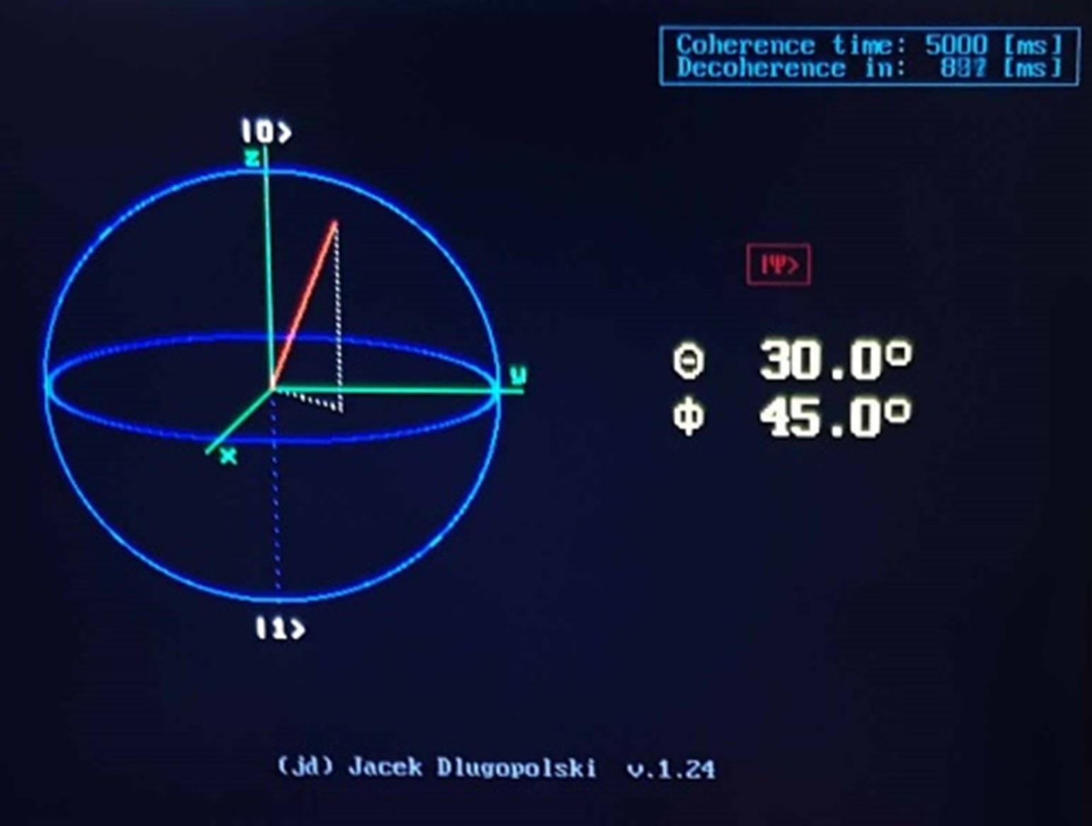
The object controlled by the system described here is an offthe-
shelf, previously realised QUBIT emulator [13] created
on the basis of an FPGA chip. This emulator represents a
qubit by means of a Bloch sphere displayed on a monitor
screen Fig. 2.
The state of the qubit is therefore determined by two
angles: 𝜃 (THETA) and 𝜙 (PHI). The THETA angle determines
the superposition level and the PHI angle determines
the phase of the modeled qubit |𝜓⟩, according to the
formula (1):
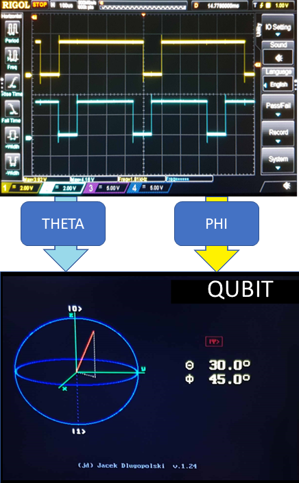
As in real quantum systems, the values of THETA and
PHI angles here cannot be set directly. The user can only
set the initial state of the entire qubit to |0⟩, and then, using
a series of electrical pulses of specific lengths, must make
the appropriate rotations of the qubit state vector so as to
obtain the intended new qubit state. Control pulses must
be formed with an accuracy of 1 µs. Schematically this is
shown in Fig. 3.
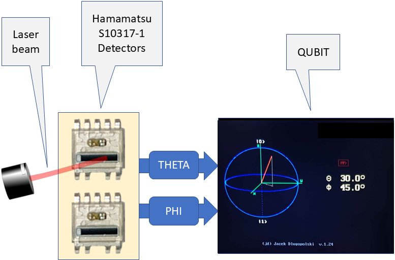
In order to make it possible to control the qubit with
pulses of laser light, a suitable circuit was built to convert
the light pulses into proper electrical pulses. High-speed
specialised Hamamatsu S10317-1 detectors [14] were used
for this purpose. This is shown schematically in Fig. 4.
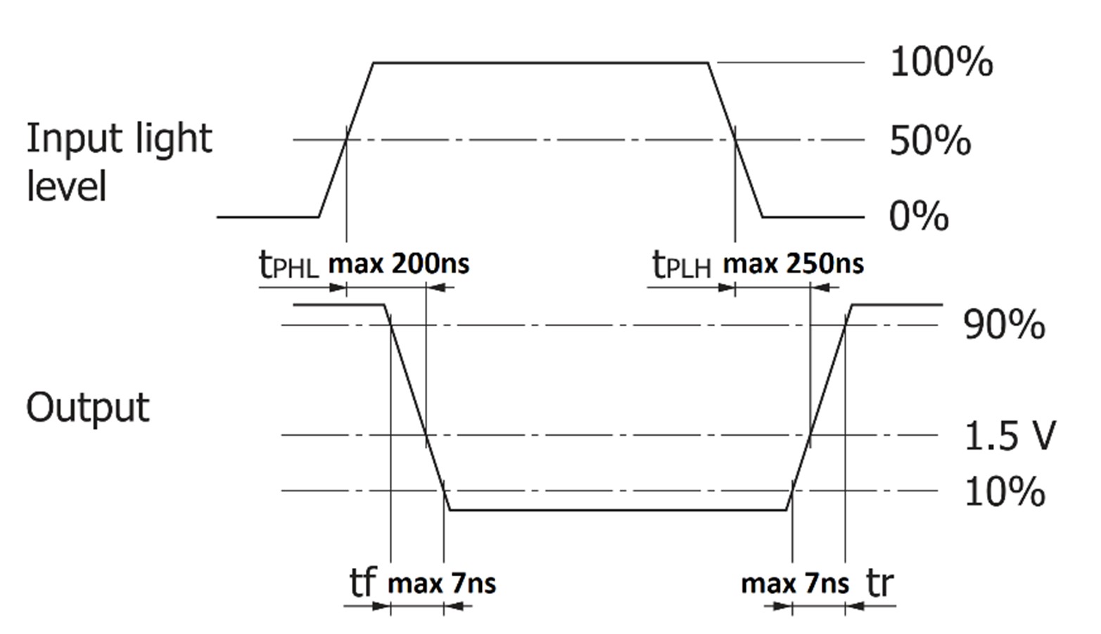
After such modification, the QUBIT can be controlled by
pulses of laser light. However, what is required is the ability
to form pulses of light of micro- and millisecond lengths
with an accuracy of 1 µs. The Hamamatsu S10317-1 detectors
selected and used here have good enough performance
to cope with proper conversion of this type of light pulses.
These parameters are shown in Fig. 5.
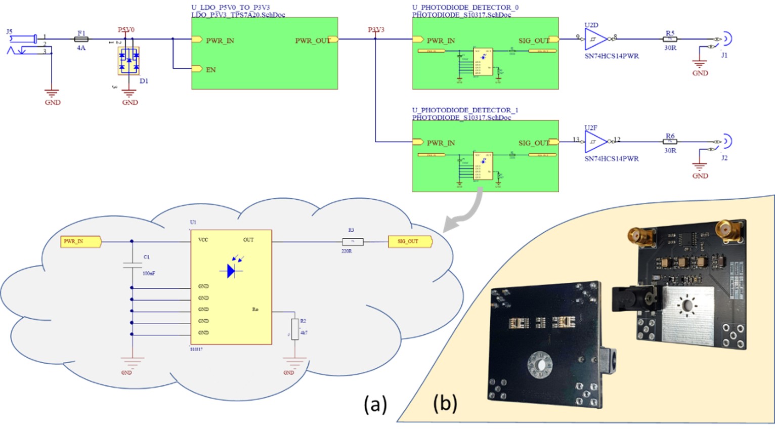
In order to achieve such fast conversion of laser light
pulses into corresponding electrical pulses, a special module
with laser light detectors was designed in Fig. 6(a) and
physically built in Fig. 6(b).
Fig. 6.Electronic schematic of the laser light detection module
(a) and photos of the physical device made (b).
Once the module is connected to the QUBIT emulator,
the emulator is able to respond correctly to the controlling
pulses of laser light and it is then possible to optically manipulate
its quantum state.
Optical laser light pulse formation system
In order to control a properly prepared qubit emulator with a
laser, it is necessary to build two cooperating optical blocks:
an optical pulse-forming block and an optical detectoraddressing
block. Both optical blocks are based on their
own AOM modulator and its driver, and are controlled using
GENMET, built on a high-speed FPGA programmable
chip. Among other things, the GENMET device performs
the electrical pulse generation functions needed here and is
described in detail in the QUBIT emulator paper [13]. The
electrical pulses generated by GENMET are used to control
the AOM modulators that form precise pulses of laser light
and to properly deflect the laser beam to address the correct
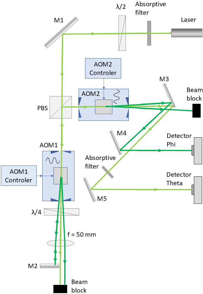
detector (THETA or PHI). The designed optical system is
shown schematically in Fig. 7.
Fig. 7.Schematic of an optical system with a double-pass circuit
for forming laser light pulses and addressing light detectors.
𝜆/2 – half-wave plate, M1,M2,..,M5 – mirrors, PBS
– polarising beam splitter, AOM1(2) – acousto-optic modulator
1(2), 𝜆/4 – quater-wave plate, f = 50 mm – lens with
focal length of 50 mm.
The light emitted by the laser goes through the absorptive
filter and then through the 𝜆/2 wave plate to clean the polarisation
and set it to the desired linear orientation. Then
light passes through polarising beam splitter (PBS), AOM1,
𝜆/4 wave plate (changing the polarisation to circular), and
collimating lens. Then the undesired diffraction orders are
being blocked and the desired one is being reflected by mirror,
upon which the polarisation is being rotated by 90◦
hence switching it to a circular direction opposite to the
incoming beam. The returning beam passes second time
through the lens and quater-wave plate on which the polarisation
is again changed but now from circular to the linear
– which results in the beam being perpendicularly polarised
to the incoming beam. The laser beam then passes through
AOM1 once again and is then reflected by the PBS and
guided to AOM2. After passing through AOM, the unused
diffraction order is being blocked while the useful ones are
being guided to designated light detectors.
The fragment built on the AOM1 works in a double-pass
arrangement and allows the laser light beam to be switched
on and off very quickly and efficiently. This makes it possible
to form pulses of light with an accuracy of the required
one microsecond. On the other hand, the second part of the
circuit built on the AOM2 is used to quickly address one
of the two detectors mounted on the control inputs of the
QUBIT emulator. The correct use and positioning of the
mirrors here effectively separates the first- and second-order
beams, allowing them to hit the THETA and PHI detectors
with ease. At any given time, one can control only one parameter
of the emulated qubit, i.e., making either a change
in the THETA angle or a change in the PHI angle.
Proof of concept
In order to examine the concept of the laser pulse control
system for the Qubit emulator described above, the entire
optical system was assembled, checked and finally connected
to the QUBIT emulator, and then the whole thing
was practically tested. The most significant components
employed in the construction of the entire prototype system
are as follows:
1 x QUBIT emulator
1 x DPSS 532 nm Green Laser SDL-532-300T
2 x AOM
2 x AOM-controller
2 x Light detector
1 x GENMET generator
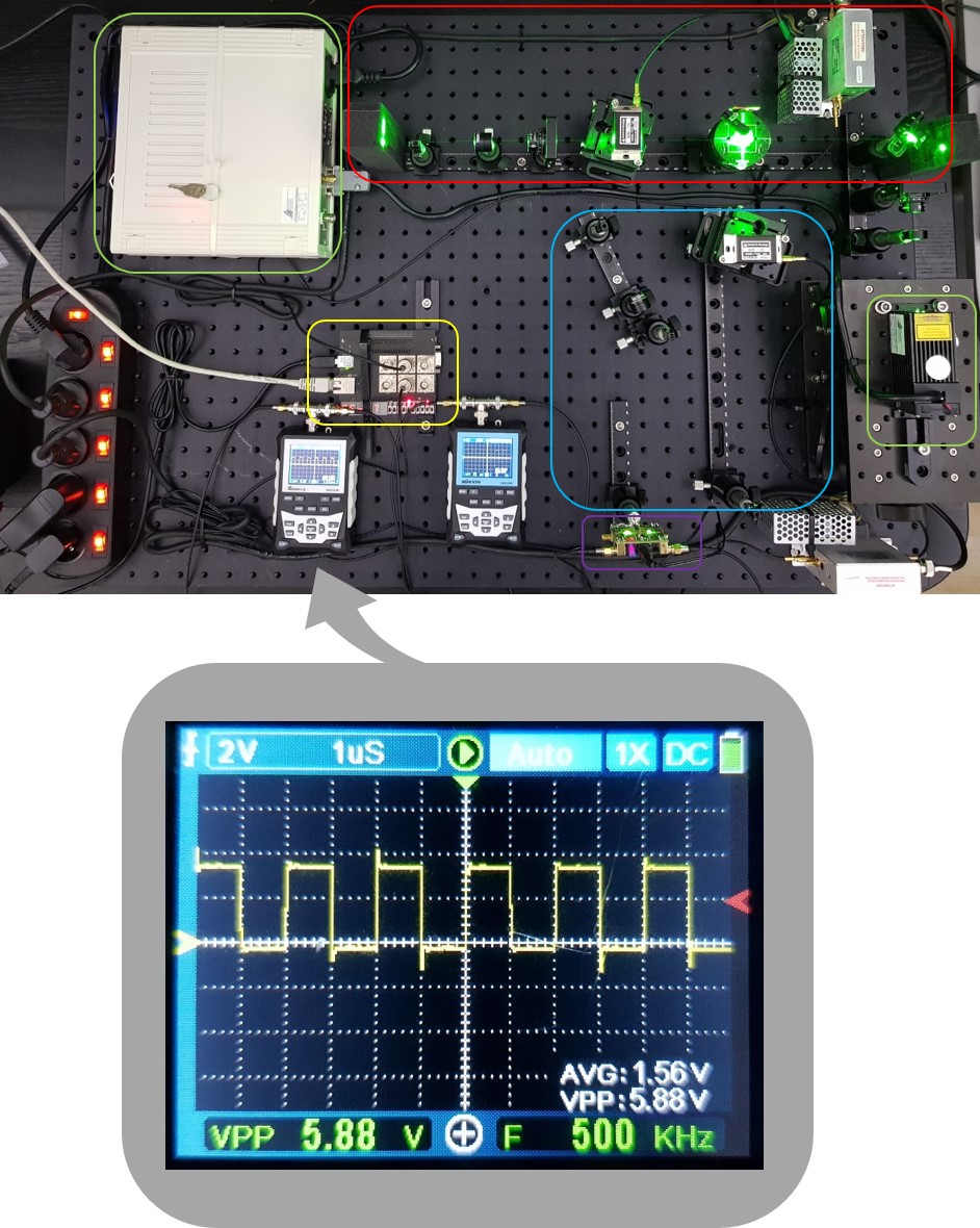
The final result of the assembled optical system is shown
in Fig. 8.
Fig. 8.The assembled optical system with an FPGA-based device
for forming pulses of laser light.
The laser and its power module have been circled with
a green line. A 532 nm laser was chosen because of its
relatively low cost, high availability, and ease of optical
system assembly, as green light is easily detectable by the
human eye. Unfortunately, most lasers used to manipulate
qubits in real ion traps are often expensive or operate in
wavelengths invisible to the human eye, which makes optical setup alignment difficult and also increases its cost due
to the price of optical components. Therefore, we had to
choose a different wavelength in order to demonstrate proof
of concept at a relatively low cost. Another important factor
was the performance of the AOMs used with 532 nm
light, high diffraction efficiency at lower RF powers compared,
for instance, to red or infrared wavelengths. The red
line marks the AOM-based optical double-pass path used
to form pulses of laser light. The blue line indicates the
AOM-based optical path for addressing the detectors. In
contrast, the detectors themselves are marked with a purple
line. The device controlling the two AOMs, based on a programmable
FPGA chip, is marked with a yellow line. The
photograph also shows two oscilloscopes connected to both
detectors. During system testing, these oscilloscopes were
used to check the correct length of the formed pulses and
the correct deflection of the laser beam to both detectors.
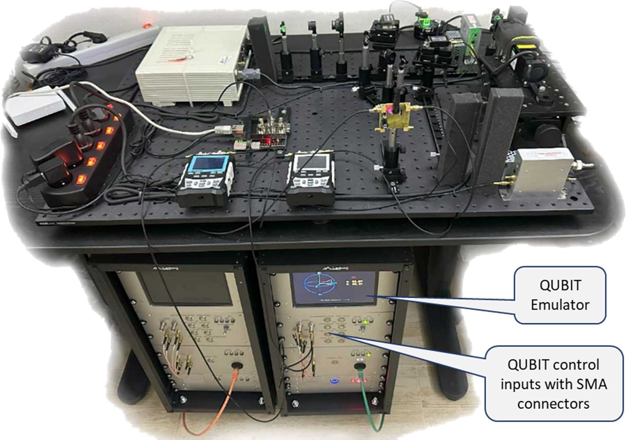
In Fig. 9 presented below, the designed optical system
(top) controls the QUBIT emulator (below on the right).
The two light detectors were connected via shielded cables
with SMA connectors to the respective THETA and
PHI inputs of the QUBIT emulator. As already mentioned,
an FPGA-based GENMET [13] device is used to control
the AOM modulators. Two output channels of the device
(OUT1 and OUT2) are used here. The OUT1 channel controls
the AOM1 modulator and is used to key the laser beam
to form pulses of light of the desired length with an accuracy
of one microsecond. The OUT2 channel, on the other
hand, controls the AOM2 modulator and is used for splitting
and deflecting the laser beam to effectively address the
selected light detector. This enables independent control of
the THETA angle or PHI angle in the connected QUBIT
emulator.
For example, to set the state of the qubit to THETA = 46◦
and to PHI = 75◦, the following steps must be performed in
the emulator:
Turning off the active signal to AOM1 to disable the laser
beam in the double-pass circuit.
Turning off the active signal to AOM2 to set the THETA
detector addressing.
Generating with AOM1 a pulse of laser light with a duration
between 9000 µs and 9100 µs to reset the THETA
angle to zero, that is, to set the qubit into the quantum |0⟩
state.
Generating a 460 µs pulse of laser light with AOM1 to
change the THETA angle of the state vector by 46◦.
Enabling the AOM2 constant active control signal to set
the PHI detector addressing
Generating with AOM1 a pulse of laser light with a duration
between 9000 µs and 9100 µs to reset the PHI angle
(qubit phase) to zero.
Generating a 750 µs pulse of laser light with AOM1 to
change the PHI angle of the state vector by 75◦.
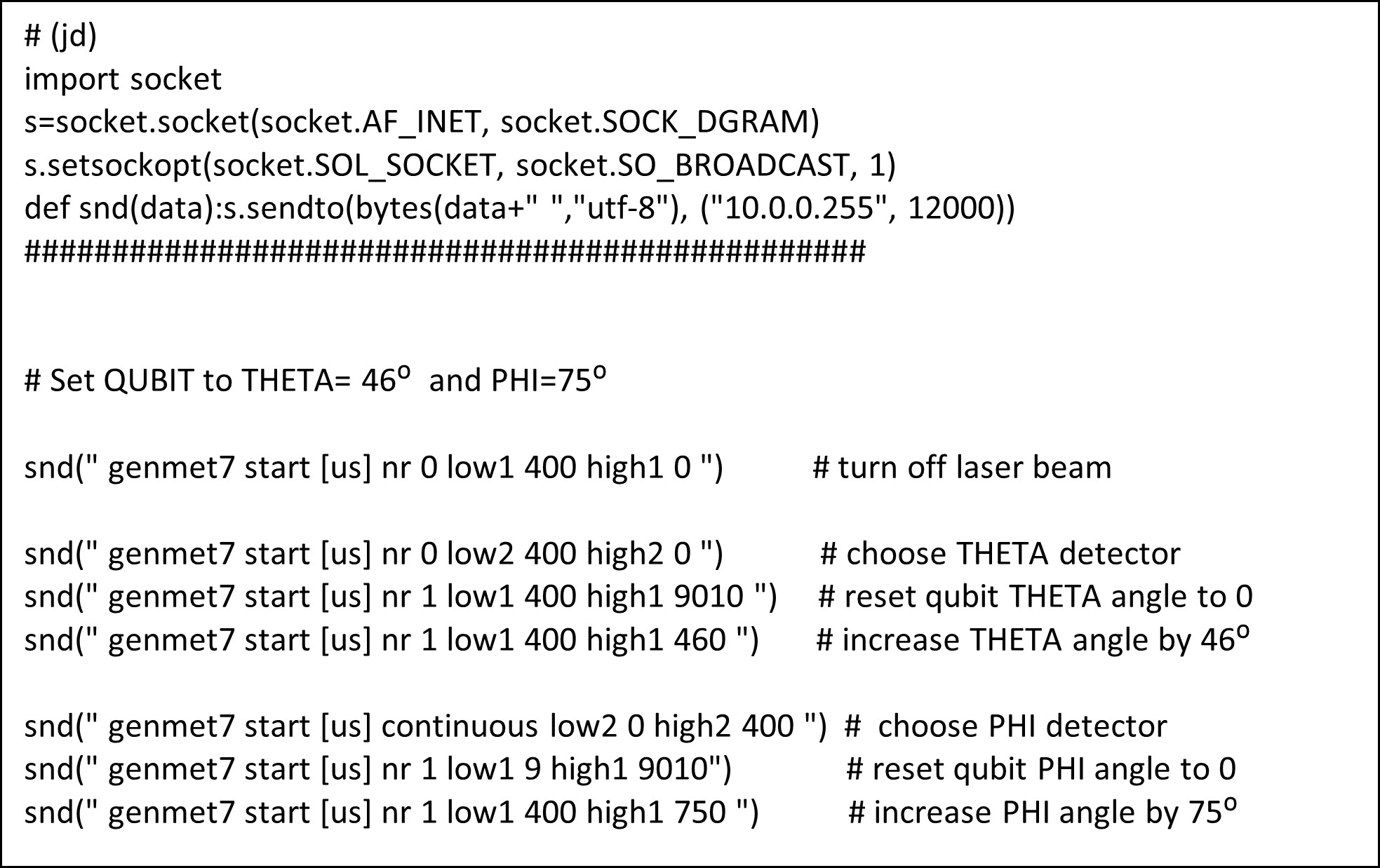
An example Python script that implements the above sequence
is shown in Fig. 10.
Fig. 10.Python script to set qubit to THETA = 46◦ and PHI = 75◦.
The upper part of the script is the appropriate preparation
of the socket for sending user datagram protocol (UDP)
type packets to the GENMET device controlling the AOM modulators. The lower part of the script, on the other hand,
implements the sending of UDP packets initiating the creation
of a series of laser pulses sent to the corresponding
detectors to set the QUBIT emulator into the required quantum
state.
The laser control of QUBIT tests has yielded positive
results, thus confirming the validity of the concept presented
here. The pulses of laser light produced by the built optical
system allow the THETAangle and PHI angle to be changed
with an accuracy of 0.1◦ and therefore allow any operation
to be performed on the controlled qubit.
Achieving an angular precision of 0.1° requires a good
quality laser with minimal fluctuations and also thermal stability
in all the optical and electronic components. The components
used in the described platform provide the abovementioned
conditions. It is also important to ensure low
and stable external lighting because it affects the operation
of optical sensors. In this case, it is the user’s responsibility
to provide a suitable space for experiments.
Conclusions
The system described in this article is sensitive to thermal
and lighting conditions, among other things. External lighting
affects the operating thresholds of the optical sensors,
so it is important to minimise external light intensity and
ensure that it remains constant during experiments. Thermal
stability must also be considered. The setup achieves
full thermal stability approximately 15 minutes after powering
up. However, these aspects are advantageous here
because, as mentioned above, similar problems are encountered
in laser systems that control real quantum installations.
Observing these dependencies on the test platform prepares
users for the problems they will face when controlling qubits
in a real ion trap.
Therefore, the concept presented in this article of controlling
the QUBIT emulator using pulses of laser light can
provide a very interesting platform to gain the necessary basic
experience even before building the final quantum systems.
The features of the QUBIT emulator itself, equipped
with functions for applying internal and external noise to
the current state of the qubit and functions for emulating
the decoherence phenomenon, now further supplemented
by the ability to form laser control pulses, provide a substantial
opportunity for initial insight into the problems of
controlling quantum systems and how to deal with them.
The tests carried out on the built system showed its proper
operation. With a single laser, it is now possible to control
two independent parameters of the qubit, and this is done
with very short pulses of laser light, as is the case in many
real-world quantum systems. Future upgrades to the proposed
optical system are planned, for example, to enable
control of more than one qubit. In that case, however, it
will be necessary to replace the AOM modulator, used here
to address the detectors, with an acousto-optic deflector
(AOD), which allows the laser beam to be freely deflected
over a wider range. Therefore, with AOD, we would be
able to address more detectors. For example, the ability to
address four detectors would allow us to effectively control
two qubits. Such an upgrade will therefore make it possible
to build laser-controlled quantum emulators for multiqubit
systems, and thus also allow testing of multiqubit quantum
gates. It is worth mentioning that such solution was also
already tested and implemented in the real ion trap-based
quantum computer [18]. Thus, use of AODs in the future
in the upgraded version of developed platform can be considered
fair and reasonable in order to better understand the
setups used in real quantum computer projects.
The platform presented in the paper allows for the control
of two parameters (THETA and PHI) of a single qubit.
Only one of them can be controlled at a time. It is not possible
to control both parameters simultaneously, due to the use
of only a single laser. Implementation of controlling both parameters
simultaneously would require adding another laser
or splitting the main laser beam, which would significantly
increase installation costs. Each additional qubit adds two
more parameters to control, requiring two additional independent
laser beams and two AOMs. With a larger number
of qubits, this approachwould not be economically viable. It
would also be difficult to implement in practice, if only because
of the size of the lasers and optical path components.
References
Preskill, J. Fault-tolerant quantum computation. In Introduction to Quantum Computation and Information, 213–269 (Caltech, 1998). https://doi.org/10.1142/9789812385253_0008.
Bengtsson, I. & Życzkowski, K. Geometry of Quantum States: An Introduction to Quantum Entanglement (Cambridge University Press, 2006). https://doi.org/10.1017/CBO9780511535048.
Childs, A. M., Leung, D., Mancinska, L. & Ozols, M. Characterization of universal two-qubit Hamiltonians. Quantum Inf. Comput. 11, 0019–0039 (2011). https://doi.org/10.26421/QIC11.1-2-3.
Guérin, S. & Jauslin, H. R. Control of quantum dynamics by laser pulses: Adiabatic floquet theory. Adv. Chem. Phys. 125, 147–267 (2003). https://doi.org/10.1002/0471428027.ch3.
de Vivie-Riedle, R. & Sundermann, K. Design and interpretation of laser pulses for the control of quantum systems. Appl. Phys. B 71, 285–292 (2000). https://doi.org/10.1007/s003400000354.
Ma, Y. et al. Precise pulse shaping for quantum control of strong optical transitions. Opt. Express 28, 17171–17187 (2020). https://doi.org/10.1364/OE.389700.
Mizrahi, J. et al. Quantum control of qubits and atomic motion using ultrafast laser pulses. Appl. Phys. B 114, 45–61 (2013). https://doi.org/10.1007/s00340-013-5717-6.
Day, M. L., Low, P. J., White, B., Islam, R. & Senko, C. Limits on atomic qubit control from laser noise. npj Quantum Inf. 8, 72 (2022). https://doi.org/10.1038/s41534-022-00586-4.
Mordini, C. et al. Multizone trapped-ion qubit control in an integrated photonics QCCD device. Phys. Rev. X 15, 011040 (2025). https://doi.org/10.1103/PhysRevX.15.011040.
Długopolski, J., Sadowski, M. & Suleja, W. A physical model of quantum bit behavior based on a programmable FPGA integrated circuit. Comput. Sci. 25, 499–519 (2025). https://doi.org/10.7494/csci.2023.25.4.6289.