Paweł Knapkiewicz1*![]()
Tymon Janisz1
Grzegorz Charytoniuk2
Michał Partyka2
Tomasz Pozniak2
Damian Stefanow3
Jakub Chołodowski3
Article info
Received 11 Oct. 2023
Received in revised form 15 Feb. 2024
Accepted 25 Mar. 2024
Available on-line 08 May 2024
Keywords: Segmented optics; CubeSat; satellite; Earth observations.
doi: https://doi.org/10.24425/opelre.2024.150604
Abstract
In current CubeSat observation satellites, the main design constraint is the available space. Standards dictating the unit dimensions of the payload severely restrict the maximum aperture and focal length of the optical instrument. In this paper, the authors present the results of work to produce a novel DeploScope optical system for a CubeSat-type observation satellite with a segmented aperture of the primary mirror deployed in space. The telescope is designed for Earth observation and is expected to find its application in the military, precision agriculture or environmental disaster prevention. The work includes a detailed analysis of the segment aperture effect on image repeatability for different numbers of main mirror segments. Based on it, the optimal configuration of the optical model of the telescope with an aperture of 188.5 mm and a focal length of 1100 mm was selected. Based on this analysis, a so-called laboratory version of the telescope was built, providing the possibility of free correction of each segment of the primary mirror while maintaining a solid stable base for other components of the module. Imaging tests were carried out on the laboratory version of the instrument and the system was optimized for a version suitable for implementation in the payload structure of the microsatellite.
In this paper, issues related to optical telescopes for space missions are raised. All elements of the optical system in the telescope are extremely important, however, the primary mirror (often for a reason) is given the status of the most important one. The bigger it is, the more imaging possibilities the telescope has. Unfortunately, the production of very large, uniform mirrors is technologically limited. An example of such a telescope is the Hubble space telescope, the primary mirror of which has a diameter of 2.4 m, and the work on its construction took two years [1].
To the best of the authors’ knowledge, a design of space telescopes with a monolithic primary mirror with a diameter larger than that of the Hubble space telescope no longer occurs. However, researchers have started to develop an optical telescope with a primary mirror consisting of many segments. The solution for the telescope with an aperture of 3 m, consisting of six hexagonal, deployable segments was presented [2,3]. A spectacular achievement in recent days was placing into orbit the James Webb Space Telescope (JWST), whose primary mirror has a diameter of 6.4 meters and consists of 18 hexagonal segments [4–8]. It is currently the largest and most complex telescope in space. There are also known plans for the LUVOIR mission, where it is planned to build an on-axis telescope with a primary mirror with a diameter of 16.7 m, consisting of as many as 36 hexagonal segments (LUVOIR-A). In the LUVOIR-B mission, it is planned to perform an off-axis telescope with an 8 m primary mirror in diameter [9, 10].
The solutions described so far are undoubtedly specta-cular and bring, or will bring, a lot of valuable information that will bring humanity closer to understanding the history of the universe.
What is of particular interest to the authors and at the same time is the subject of this article, is the construction of optical instruments for Earth observation for CubeSat platforms. The main area of interest are solutions with a segmented and deployable primary mirror.
For the needs of CubeSat satellites, methods of unfolding the secondary mirror or components of classical optics (lenses) are developed [11–13]. This is a very interesting direction to minimize the construction of satellites whose volume is ready to be launched. Such solutions are not the subject of this article and will not be discussed later.
The first idea of a sub-meter resolution satellite with an optical instrument consisting of a segmented aperture was presented by Dolkens [14, 15]. He proved theoretically that it is possible to build a telescope with dimensions appropriate for MicroSatellite platforms, where the primary mirror will consist of three petals. He proved that from an altitude of 500 km, it is possible to obtain a ground resolution (ground sample distance – GSD) of 25 cm. Similar considerations were carried out in Ref. 16, where a solution for the 3U CubeSat observation satellite with a deployable primary mirror was proposed. The primary mirror consists of four petals and the GSD is estimated to be less than 1 m from an altitude of 350 km. Champagne et al. [17] developed this idea into a laboratory version by introducing an optical instrument whose primary mirror consists of four petals, creating a segmented aperture of 200 mm. The instrument has a GSD of 1.5 m with an altitude of 500 km.
This work contains a feasibility study, tests, and their verification in laboratory conditions of an optical instrument with a segmented aperture. The work undertaken by the authors aims to develop an optical instrument with a segmented and deployable aperture and an active secondary mirror with a precise position correction. The ability to actively correct the position of the mirrors can correct errors caused by solar radiation [18] or vibrations [19]. Active counteracting these changes, especially in the context of building a small observation satellite, seems to be extremely important to achieve the best possible optical parameters of the instrument.
Comparing known telescope designs, the Korsch system has been chosen because of its trade-off between mass, size, and optical properties [20, 21]. The main guidelines for the telescope design were to divide the secondary mirror aperture into several petals, which, in further work, is to enable the construction of a telescope with deployable primary mirrors and the optical instrument (excluding detector) in the folded state is to conform to the 2U structure of the CubeSat standard (10 × 10 × 20 cm3). The 2U of volume dedicated to the optical payload is a basic assumption for the design. The idea is to develop an optical payload that can be integrated with a 6U or 8U structure, which are the sizes of CubeSat satellites that are the most optimal in terms of production and launch costs.
CubeSat refers to a type of miniaturised satellite that typically adheres to a standardised form factor. These small satellites are modular, constructed in units or cubes of 10 × 10 × 10 cm (1U) or multiples thereof (2U, 3U, and so on). This standardised sizing allows for easier integration and deployment. CubeSats were initially conceived for educational and research purposes due to their compact size and relatively lower cost compared to traditional satellites. However, they have found increasing applications in various fields, including scientific research, Earth observation, technology demonstration, telecommunications, and more. Their modular nature allows for flexibility in design and payloads. While their size limits their capabilities compared to larger satellites, advancements in technology have led to increased functionalities in CubeSats. Despite their small size, CubeSats contribute significantly to space exploration and research due to their ability to facilitate rapid and cost-effective access to space. They often work collaboratively in constellations or networks to achieve specific scientific or operational objectives. CubeSat compact dimensions impose specific challenges and constraints on designing optical systems, such as ensuring that the mirrors fit within the prescribed space and considering the deployment mechanisms that must align with these spatial limitations. Balancing these constraints with optimal functionality becomes a critical aspect of CubeSat-based optical system design.
For situations where the primary mirror is segmented and the petals are planned to open after reaching an orbit, it is expected that an aperture error will be generated due to the uneven distribution of the M1 petals, and this fact is simply assumed. Therefore, it was proposed that the M2 mirror would also be segmented to compensate for the error introduced by M1 after correcting the position of the M2 petals. This approach will require development of a mechanism to precisely correct the position of each M2 petal independently. This issue will be addressed but will not be described within this article.
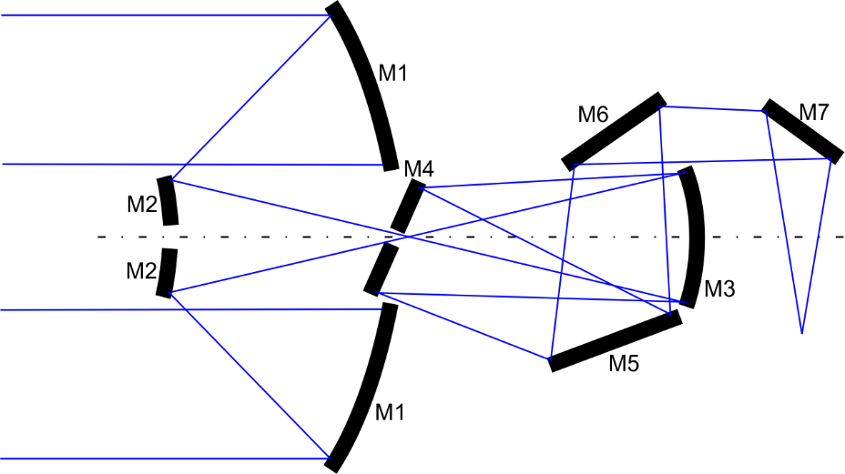
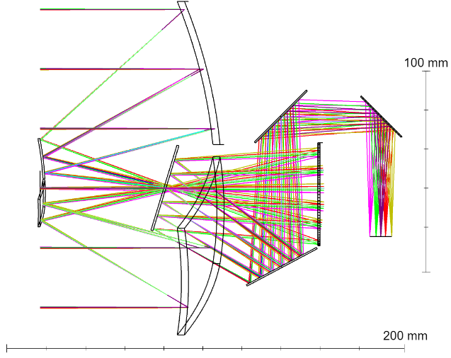
Due to given requirements, an optical design shown in Fig. 1 was proposed. The telescope consists of seven mirrors. The primary (M1) and secondary (M2) mirrors have a segmented aperture. The M3 mirror is the last curved one. The M1, M2, and M3 mirrors are responsible for the proper beam preparation, and as a result, obtaining a focal length of 1100 mm. Mirrors from M4 to M7 are flat mirrors and are required to route the beam in a 2U structure of the CubeSat standard. An interesting solution is created by a set of mirrors M2, M3, and M4, when the light reflected from M2 inverts and reaches M3, and passes through the centre hole in M4 on the way.
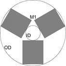
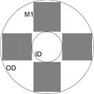
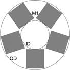
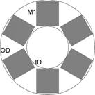
Primary mirror optical apertures with three, four, five, and six petals have been analysed (Fig. 2). It has been decided that the secondary mirror (M2) aperture would be a scaled shape similar to the primary mirror (M1) aperture. The less than three petals approach has been disqualified due to the significantly lower area of the active aperture. On the other hand, splitting the aperture into a larger number of petals increases the mechanical complexity of the mirror actuation system, including mirror segments and the segment deployment mechanisms which must also fit within the CubeSat structure.
The rectangular shape of the mirror segments was selected based on a preliminary technical analysis of the proposed solution feasibility so that the M1 segments fit inside the CubeSat structure. Regardless of the segments number, these segments cannot have a shape other than rectangular because it will not be possible to stow them. The only possibility to modify the segments shape (mirror surface) is to maintain rounding on the outside of the segments (representing the full aperture), but the gain of increasing the mirror surface would be negligible.
Due to the Korsch telescope design and an assumed fixed aperture of 180 mm, primary mirror segments – in the case of four, five, and six segments in comparison to three segments – have to be shortened to fit them all in a circular pattern. Since each of the systems planned to be simulated has a different geometry of the mirrors M1 and M2. In Table 1, the parameters of the aperture are listed: M1 outer diameter (common to all models), M1 inner diameter, M2 outer diameter, and M2 inner diameter. Additionally, the area of a single segment and the surface forming the mirror M1 and M2 were estimated.
Table 1.
The parameters of M1 aperture depend on the number of petals.
| No. of petals | M1 OD [mm] |
M1 ID [mm] |
M1 segment surface [mm2] |
M1 total surface [mm2] |
M2 OD [mm] |
M2 ID [mm] |
M2 segment surface [mm2] |
M2 total surface [mm2] |
| 3 | 180 | 20 | 3705 | 11 115 | 20 | 9 | 190 | 570 |
| 4 | 180 | 29 | 2964 | 11 856 | 29 | 18.3 | 302 | 1208 |
| 5 | 180 | 37 | 2400 | 12 000 | 37 | 30 | 398 | 1990 |
| 6 | 180 | 40 | 2021 | 12 126 | 40 | 35.2 | 391 | 2346 |
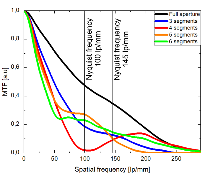
Increasing numbers of petals cause increasing in the total surface of M1 and M2. Unfortunately, this is accompanied by the increasing diameters of IDM1 and IDM2 – the linear obstruction relative to the diameter is enlarged, which has a negative effect on the point spread function (PSF) and modulation transfer function (MTF). Optical parameters of M1 have been simulated in OpticStudio software (Zemax LLC, USA). MTF was compared for different petal configurations (Fig. 3). The PSFs spot diagrams and their analysis are shown in Fig. 4. The PSF and Airy Disk radius analysis, both were simulated in OpticStudio using fast Fourier transform at a 588 nm wavelength.
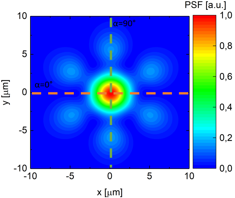

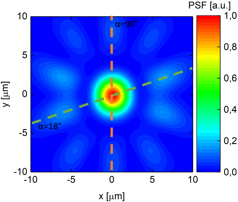
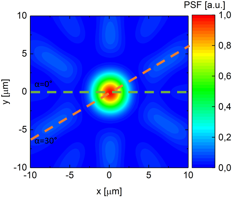
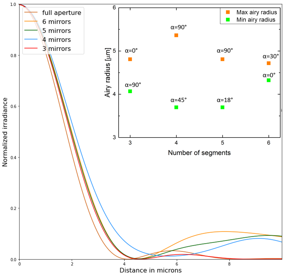
The most crucial directions have been assigned to the largest and smallest Airy Disk radius. These specific directions are indicated by dashed lines in green and orange [Fig. 4(a)–(d)], and the outcomes are summarised in Fig. 4(e). It is observed that the minimum Airy Disk radius is attainable for configurations with four and five petals. Unfortunately, the configuration with four petals also yields the maximum Airy Disk radius, resulting in the widest spread for this setup. The second-largest spread in the Airy Disk radius occurs with the five-petal configu-ration, while the narrowest spread is associated with the six-petal configuration. Considering both the smallest Airy Disk radius and the narrowest spread of the Airy Disk radius as selection criteria, configurations with three and six petals remain under consideration.
The instrument was designed for an 8.5 × 7.1 mm2 sensor and a 3.45 μm pixel size (pixel size is defined as the total area occupied by the active photosensitive part of a single pixel and the inactive part. The ratio of the active part of the pixel to its total area is defined as the Kell factor). Nyquist limit (1) is affected by pixel size and Kell factor. The Kell factor corresponds to the space between pixels and its value is ~ 0.7 usually (value 0.7 corresponds well to the selected detector).
 |
(1) |
If the Kell factor is equal to 1, the Nyquist limit reaches 145 lp/mm, but in this case, it is about the pixel pitch, not the pixel size. The true value of the Nyquist limit is achieved taking into account the spacing between pixels (Kell factor) and in the considered case it is ~ 100. The reference to the MTF parameter and the potential production possibilities are the chosen ways of validating the solution.
Setup with four petals loses contrast before reaching 100 lp/mm of the Nyquist limit, so this solution has been rejected. Among the rest of the solutions, a 3-segmented configuration shows the best performance at lower spatial frequencies (< 100 lp/mm). The 5- and 6-segmented configurations might be considered, however, the lowest performance at lower spatial frequencies (< 100 lp/mm) and mechanical design problems related to the numbers of segments disqualified this solution.
Metwally et al. [22] conducted a theoretical analysis of the telescope high-resolution satellite design. For the ultimate goal of achieving a GSD of 0.25 m, they estimated that the aperture of the primary mirror should be 1.4 m. They noted that the filled aperture design is large in volume and width and analysed a configuration with a segmented aperture of two to six petals in each of three shapes: rectangle, trapezoidal, and hexagonal form.
The analysis results show that satisfactory parameters can be obtained for configurations of two and three rectan-gular, four trapezoidal, or five and six hexagonal petals.
Considering all advantages and disadvantages, three rectangular petals solution was chosen for the development and testing.
Final optical design and ray trace were done. The shape of mirrors M1, M2, and M3 was optimized to obtain 188.5 mm of optical aperture and focal length of the telescope equal to 1100 mm. Hyperfocal has been estimated at 60 km. Mirrors from M4 to M7 are flat. Dimensions of all mirrors and their positions (position of M1 segments before unfolding) allow them to be closed inside the standard 2U structure and the beam to be guided correctly (Fig. 5). The characteristic of the designed telescope is listed in Table 2.
Table. 2.
The characteristic of the designed telescope.
| Parameter | Value / description |
| Optical aperture | 188.5 mm (mirrors inscribed in a circle of this diameter) |
| Focal length | 1100 mm |
| Primary mirror (M1) | f = 256 mm; 3 petals of 3711 mm2 active surface; 11 133 total active surface |
| Secondary mirror (M2) | f = −140 mm; 3 petals of 293.8 mm2 active surface; 881.4 total active surface |
| M3 | f = 125 mm; round mirror; Ø 58 mm |
| M4 | round flat mirror; Ø 40.74 mm; centre thru-hole Ø 6 mm |
| M5 | round flat mirror; Ø 40 mm |
| M6 | round flat mirror; Ø 33 mm |
| M7 | round flat mirror; Ø 29 mm |
| Sensor | Sony IMX250, pixel size 3.45 μm, sensor size 8.5 × 7.1 mm2 |
Being aware that the designed telescope has a segmented aperture, the authors expected a degraded image quality. Specialised software was developed for this project. Based on the theoretical parameters of the telescope, this software reproduces the image that is likely to be obtained. Modelling will be performed for one, two, and three segments concerning the full aperture.
Diffractive limitations of resolving power of segmented aperture depend directly on its complex pupil function. The bigger the “synthetic” aperture, the higher the spatial resolution and the cut-off frequency it can resolve without aliasing. The autocorrelation of the aperture function describes this effect. In our simulated ideally and co-phased telescope, it is a binary function that is characterised by the figures in the 2nd_ROW_APERTURES. In the case of a segmented aperture, additional effects will occur based on the autocorrelation of the aperture, its redundancy, and its shape.
As shown before in Fig. 4, different shapes of apertures result in different PSFs which leads to different resolving abilities, not only compared between different PSFs but also across different directions of reproduced spatial fre-quencies for the same aperture. Since the aperture function is well known, image creation for simulation purposes could be simplified to (2)
|
where: I is the image, O is the object, ![]() is the convolution, PSF is the point spread function (of simulated aperture) which is the convolution of the simulated object and PSF of the system (in this situation aperture alone), resulting in an image on the sensor. PSF can be obtained from the complex pupil function by performing a Fourier transform on it and taking the squared modulus of the result, or by performing an autocorrelation of the pupil function and performing a Fourier transform.
is the convolution, PSF is the point spread function (of simulated aperture) which is the convolution of the simulated object and PSF of the system (in this situation aperture alone), resulting in an image on the sensor. PSF can be obtained from the complex pupil function by performing a Fourier transform on it and taking the squared modulus of the result, or by performing an autocorrelation of the pupil function and performing a Fourier transform.
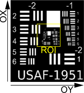
For simulation, the authors chose the well-known USAF resolution target [(Fig. 6(a)] and limited their simulation to the comparison of different shapes of the aperture. For that reason, the only factor that influences a simulated PSF is the aperture shape. The authors consider different layouts for their three mirror setups. It is clear that the shape of the PSF is responsible for resolving capabilities that are not uniform for each angle in segmented apertures. Results of this property can be seen in Figs. 6 and 7 where modulation of the contrast from line spread function (LSF) calculated for the 0–1 pattern of the USAF test target is visible. Directions in which the autocorrelation of apertures achieve higher frequencies result in better resolution in those directions [23]. This effect can be seen in Fig. 6. The resolving ability of a 3-plate aperture in the direction of axis OY [Fig. 6(b)] is not significantly better than that of 2-plate aperture [Fig. 6(c)], but when the spatial frequencies in the OX direction are compared, the difference is significant, resulting in a blurry image. Comparing the resolving ability in the OX-axis direction of 3 plates [Fig. 6(b)] and 2 plates [Fig. 6(d)], the result shows no difference, but in the OY-axis direction, a blurred image is obtained. The resolving ability of 1-plate aperture [Fig. 6(e)] is pure on both directions resulting in a blurred image.
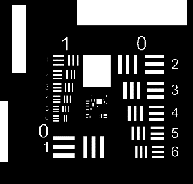

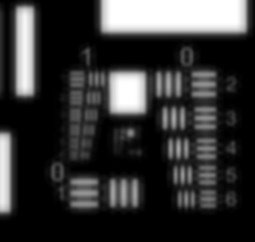


Deeper analysis shows that a fully opened aperture with three primary mirrors [Fig. 6(b)] can accurately resolve both OX and OY directions, but not as well as a 2-mirror aperture shape [Fig. 6(d)] in the case of OX direction. This is due to the blurring effect of redundant regions of aperture in that autocorrelation function which degrades the quality of resolving (object) frequencies under study. Additionally, redundant regions in autocorrelation result in additional aberrations in corresponding spatial frequency directions, but this was not included in simulations, as the authors simulated a “perfect” telescope.
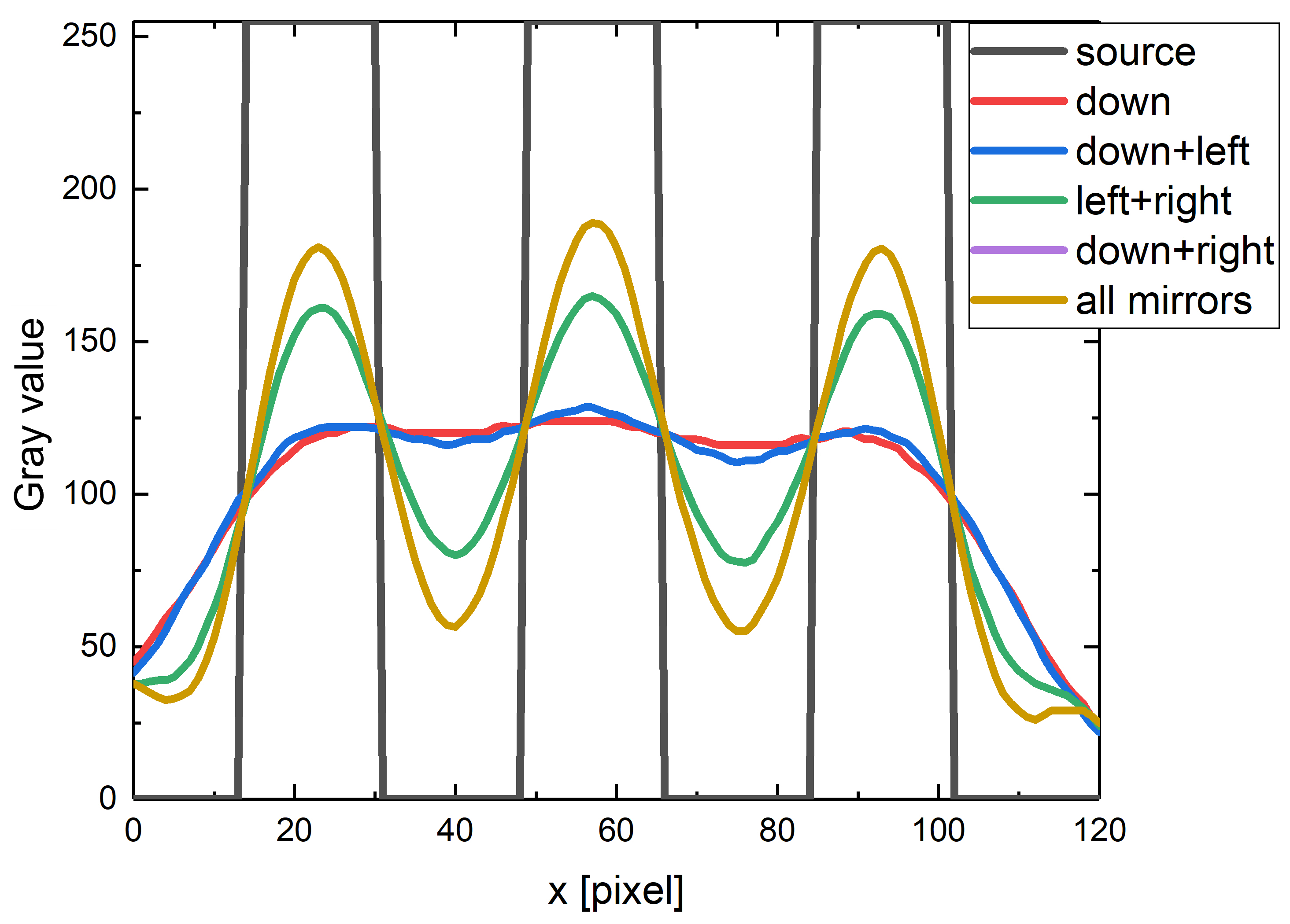
Representation of the modulation in the OX direction and differences between different shapes of aperture are shown in Fig. 7. Modulation of the object itself is marked in gray and manifested as perfect vertical slopes (perfect telescope effect). Modulation transfer functions and their adequate resolving capabilities are plotted in colours: green – three petals [see Fig. 6(b)], red – two petals in configuration presented in Fig. 6(c), yellow – two petals in configuration presented in Fig. 6(d), and blue – one petal [see Fig. 6(e)]. From blue and yellow plots, the pattern of the object cannot be distinguished.
The analysis shows that aperture segmentation negatively affects the ability to reproduce an image with more details. However, it is possible to obtain a correct imaging of the image (test pattern) for three segments as long as the segments are perfectly aligned. This conclusion is crucial to the mechanical design as described below.
The technical design of the first version of the instrument assumed that it would not meet all functional requirements, such as compatibility with the CubeSat platform mass and dimensional criteria, and interfaces with the CubeSat deployer. This model is intended to validate the assumptions made as a result of the RayTrace simulations. The main goal was to be able to recreate the target spatial alignment of the DeploScope mirrors and to test the optical system under laboratory conditions.
The structure was designed to use mechanical parts that are easy for fabrication and commercially available optomechanical parts. The DeploScope module has been placed on a solid mechanical base (CNC-machined aluminium block) on which the M1 and M3–M7 mirror modules were placed

The key consideration for this version of the module was to ensure that the position of M1 mirrors could be freely adjusted in as many axes as possible. Precise control of many degrees of freedom is very difficult [24], therefore, in the laboratory version of the telescope, the authors have limited the number of degrees of freedom to five. M1 mirror segments were placed on 5-axis PY005 stages (Thorlabs) providing movement in five degrees of freedom for each: translations in OX, OY, OZ and rotations in OX and OY.
The crucial element of the DeploScope module was a monolithic aluminium structure to which the end elements of the optical path (M3–M7 mirrors) were attached. Like the base, this module was made from a single block of aluminium to ensure rigidity and stability. The precise geometric reproduction of the component (as defined in section 2.1 of this paper) ensured that no additional mechanical correction of the mirrors was necessary. The final component of the optical path was a JAI Go 5100-PGE camera moving on an aluminium rail providing a single-axis positional adjustment.
To simplify the fabrication and reduce the number of positioning mechanisms for segments of the secondary mirror (M2), secondary segments were made as an aluminium monoblock with protruding mirror surfaces [Fig. 8(b)]. The entire M2 module was mechanically separated from the main DeploScope structure and placed on a dedicated structure consisting of ThorLabs linear translation stages providing adjustments in OX, OY and OZ axes. The separation of the M2 module from the rest of the structure of the Deploscope laboratory version is intended to increase the possibility of repositioning M2 mirrors for different imaging test configurations.
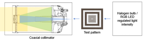
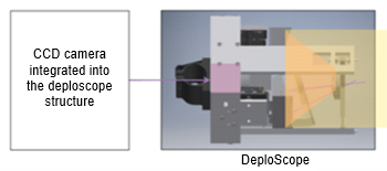
The developed telescope was tested on optical test bench equipped with a coaxial collimator with an aperture of 203 mm and a focal length of 2436 mm. This system simulates real conditions in laboratory conditions where the target is hundreds of kilometres away (in the notation for a telescope at infinity) [25]. Any test patterns can be used in the stand, including commercially available test paters on glass or photographic film for example. The light source is a halogen or an RGB LED lamp, both with a controlled light intensity (Fig. 9).
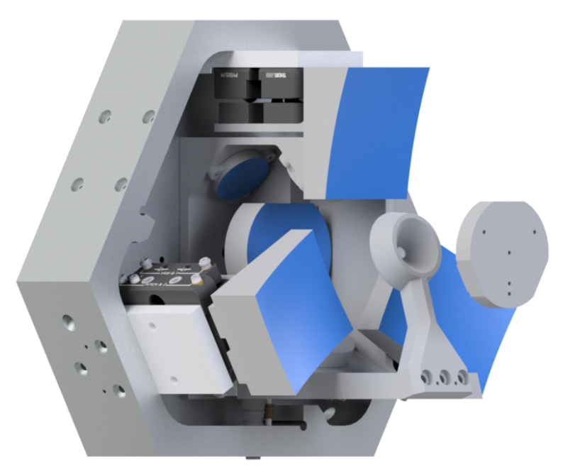
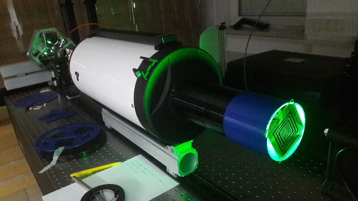
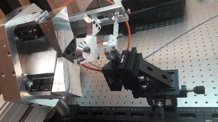
The test bench prepared for measurements is shown in Fig. 10(a). A detailed view of the DeploScope optical instrument showing the structure with mirrors M1, M3–M7 attached and mirror M2 mounted on the stage enabling its positioning in the XYZ axes is shown in Fig. 10(b).
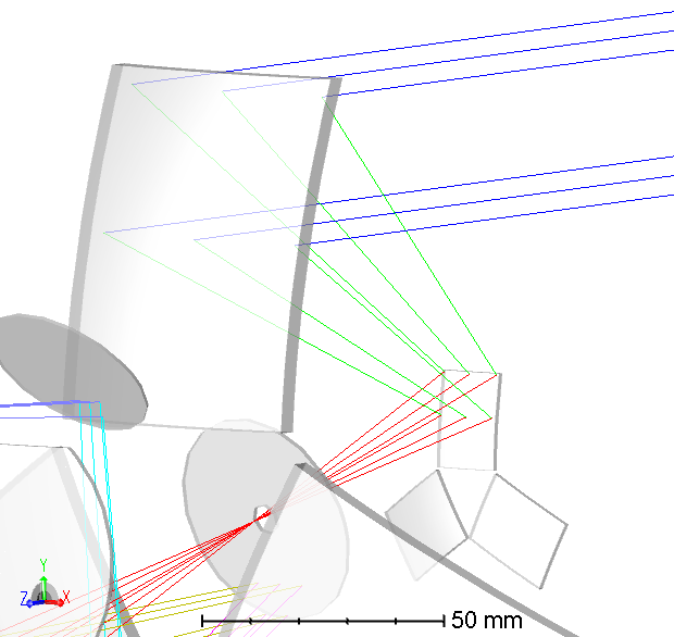
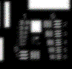
DeploScope tests began with setting pairs of M1 and M2 segments in the correct positions. This process was performed independently for each pair of M1–M2 segments. During the calibration of the selected pair, the remaining segments of the main mirror were obscured. This resulted in obtaining three identical, shifted images. These images correspond to the three optical paths which are defined by the three mirror segments (pairs M1 and M2, Fig. 11).

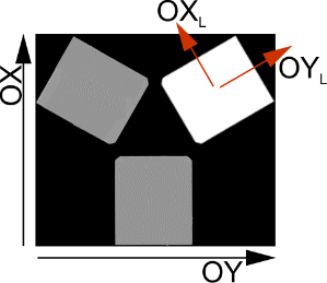
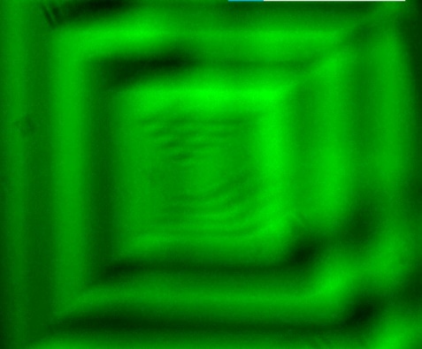

After changing the test pattern, the contrast transfer was examined. Figure 12 shows the effect of this test for one of the segments oriented at an angle with respect to the main optical axes [Fig. 12(a)]. The configuration of an optical pattern, which is oriented toward the main optical axis, is blurred [Fig. 12(b),(c)]. The reorientation of the optical pattern to the position consistent with orientation of the edge of the mirror segment resulted in an increase in the optical reproduction contrast in one of the axes of the local petal coordinate system (OXL, OYL). The test result is consistent with the theoretical considerations discussed in the previous section.
In the next step, the images were fine-tuned. This process required precise adjustment of the position of the primary mirror segments. The positions of the M1 segments were corrected independently, and the image adjustment process required:
- obtaining the correct imaging, which means a projection of the test pattern more or less in the middle of the detector independently for each M1 segment (one segment was active where other two were covered),
- then, to one of the images (let us assume M1-1) the other one (M1-2) was tuned; this required a correction of the position of the segment M1-2, but also a small correction of the position of M1-1,
- finally, to the M1-1 and M1-2 images coordinated together, the image M1-3 was tuned; as before, this required a correction of the position of segment M1-3, but also a slight correction of the position of M1-1 and M1-2, so the last step was the most difficult.
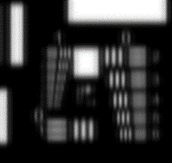
The effect of this action was to obtain an image correctly reflecting the test pattern (Fig. 13).


It is necessary to refer again to section 2.1. Optical design, where it was assumed that the position error of the M1 segments will be corrected by the segmented mirror M2. As a reminder, the M2 was made as a single block and in this version of the telescope it is not possible to correct the position of a single M2-x segment and perform fine image correction.
However, it should be emphasised that the obtained result is satisfactory and consistent with the goals of building the first laboratory version of DeploScope.
Comprehensive work was carried out on the development of a sub-meter resolution telescope with a segmented aperture dedicated to the CubeSat platform. The research began with a detailed analysis of the impact of the segmented aperture on the image reproducibility. As a result of this analysis, an optical model of the telescope with an aperture of 188.5 mm and a focal length of 1100 mm was proposed.
A laboratory version of the optical instrument was built. A feature of this solution is the possibility of indepen-dent and precise correction of the position of each segment of the primary mirror. The secondary mirror is segmented, but for simplicity of design, the segments are on a solid block. The telescope, called DeploScope, was tested in laboratory conditions. Correct imaging was obtained and the segmented aperture was proven possible in space-based telescopes intended for CubeSat integration.
The ability to deploy the segments of the primary mirror has several advantages. First of all, it is possible to close the instrument (stowed primary segments) in the outline of 1U (in the plane of the optical axis), what fully conforms to the CubeSat standard. This in turn facilitates the launch of several satellites at one time and lowers launch costs. Secondly, the unfolding primary mirror segments significantly increase the aperture from about 80 mm (the maximum value for standard telescopes for CubeSat) to 188.5 mm obtained in this solution.
Unfortunately, the segmented aperture design of the M1 has its drawbacks. The most important of these is a signifi-cant reduction in the MTF factor. Although the theoretical GSD can reach 1 m from a height of 350 km, the image quality remains unsatisfactory. Hence, it is crucial to inquire: will the design discussed here offer benefits over existing optical tools specifically designed for CubeSats?
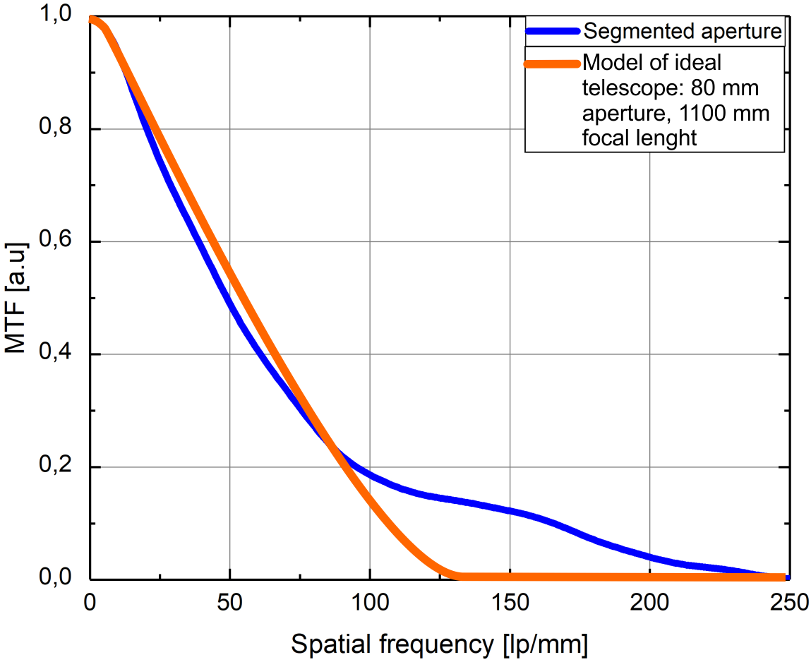
The answer to this question can be given by comparing telescopes with similar parameters. Telescopes available on the market that can be built in a 1U outline in the optical axis have a maximum aperture of 80 mm and a focal length of ~ 300 mm. These are fundamentally different parameters to compare the two telescopes. Therefore, DeploScope parameters were compared with the MTF factor of the numerical telescope model with an 80 mm aperture, a 1100 mm focal length, and an estimated linear obstruction of ~ 8.9 mm (Fig. 14). For this ideal telescope, it is seen that the MTF parameter drops steadily to zero (< 125 lp/mm), when DeploScope shows better performance at higher spatial frequencies (100 lp/mm – 250 lm/mm).
The short analysis proves that it is justified to develop the technology of telescopes with segmented aperture and deployable primary mirror petals. Summing up all the work done, it should be stated that a comprehensive research was carried out on the possibility of designing, manufacturing, and testing in laboratory conditions a telescope with a segmented aperture and obtaining the correct imaging.
This so-called “laboratory version” is a technology demonstrator being developed by the research team. Currently, the work is underway on a version of the telescope with deployable primary mirror segments and a module of secondary mirror with precise correction of the position of each of the M2 segments. This approach is to enable the correction of the M1 segment distribution error and to respond dynamically to changes related to thermal exposures (the Sun).
Authors’ statement
Research concept, P.K.; the idea inventor, T.P.; optical design, T.P. and G.Ch.; mechanical design, D.S. and J.Ch.; collection and/or assembly of data, T.J.; optical analysis and interpretation, M.P.; writing the article, P.K. with support of G.Ch. and M.P.; critical revision of the article, P.K.; final approval of article, P.K.
Acknowledgements
The work has been developed and financed under the Project entitled: “Development of a revolutionary Earth imaging service using the satellite REC constellation”, under Measure 1.1.1 of the Intelligent Development Operational Program 2014–2020. Project co-financed by the European Regional Development Fund, agreement number: POIR.01.01.01-00-0824 / 19-00.
References